it's a while i play micro controller
but for restart order:
ESP32 C6
IDE
unpack and BLINK test
1M loop test
WiFi and Advanced Webserver
check 16MB flash
check WiFi signal
Power Meter Project
ESP connect
play some tutorial
Micro-Python update
ESP32 C6
i want to use 'shopee' online shop because i get most of the things there
( even need some weeks after available like at amazon.com )
but not need to use a credit card,
COD "Cash on Delivery" means a SHOPEE motorbike brings the stuff to my gate and i pay cash (THB)
over the time i see many esp32-c6 in the 'super mini' format
with the small ceramic antenna
read that some only work on short distance even theoretically it should be better as the PCB antenna
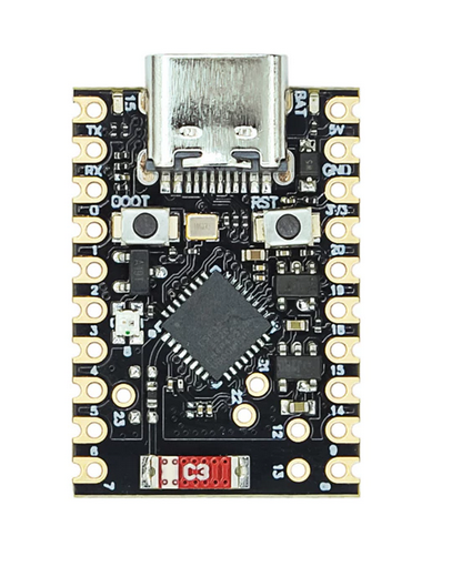
( i might order one of these later as, well, can't play with some new things if not have 2 of them / still my LAN is NOT WIFI 6 )
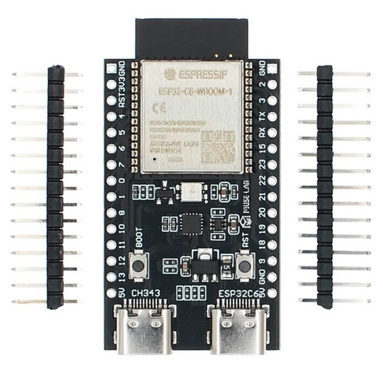
but now see the big board with the 2 USB C ports like
* one for programming of the ESP module and
* one for Human Interface Devices (HID) via a add CH343 USB chip to TTL to ESP module
and the original ESP32-C6 WROOM-1 module.
its a ESP32-C6-DevKit C N(4/8/16)
clone, but sure, the ESP module is original!
i order yesterday and today it's 'SOLD OUT' hope i not get some garbage production,
but it was only 180THB about 4.76EUR for the N16 version ( delivery free for our account ) ( incl. pin-headers but NOT soldered )
N16 is 16MB flash
so, what is special about
C6
( compared to C3 ? )
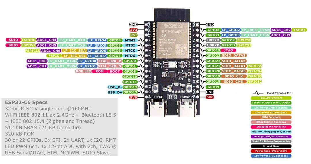
CPU
* 32-bit RISC-V single-core microprocessor, up to 160 MHz
Memory
* ROM: 320 KB
* HP SRAM: 512 KB
( i see in online shop like
R2 but must confirm later if there is a external 2MB serial RAM ( as i know it from the ESP32 S3 ) )
* external SPI flash 4 / 8/ 16 MB
WIFI
* 2.4 GHz Wi-Fi 6 (802.11ax)
* Bluetooth® 5.3 (LE)
* Zigbee 3.0
* Thread 1.3 (802.15.4)
* Matter and ESP RainMaker Integration
wroom-1 datasheet
IDE
i will use primary the Arduino IDE ( have to check it does 'C6' modules now )
( or possibly test Micro | Circuit Python again )
but as my Arduino IDE is older 2.3.6
better download the new one from
https://www.arduino.cc/en/software/
arduino-ide_2.3.8_Linux_64bit.zip ( 202MB )
see old
BLOG for new install,
now only need update ( on my AM5 Ubuntu 25.10 PC ):
cd /opt
sudo unzip ~/Downloads/arduino-ide_2.3.8_Linux_64bit.zip
sudo ln -sf arduino-ide_2.3.8_Linux_64bit/arduino-ide arduino-ide
cd arduino-ide_2.3.8_Linux_64bit
sudo chmod 4755 chrome-sandbox
now start that app / new version ( pls check ) / from desktop icon
and update libraries and boards.
/menu/tools/board/ select:
ESP32C6 Dev Module
now check out the ESP32C6 Examples, that is insane how many ...
i even found a
* Zigbee Gateway
that was what i was hoping for,
like when i buy a second board ( the small one ) and use it as ( example )
* Zigbee_On_Off_Switch...
together that would be my first ZIGBEE network and
possible can operate from phone or PC
ok, wait for hardware
28.3.2026 that was fast
unpack and BLINK test
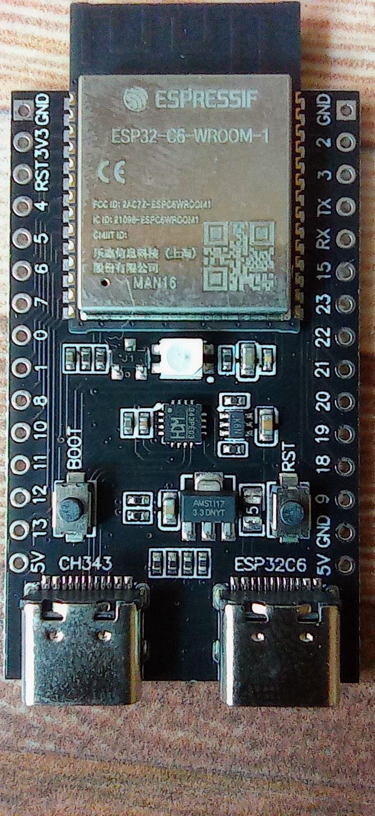
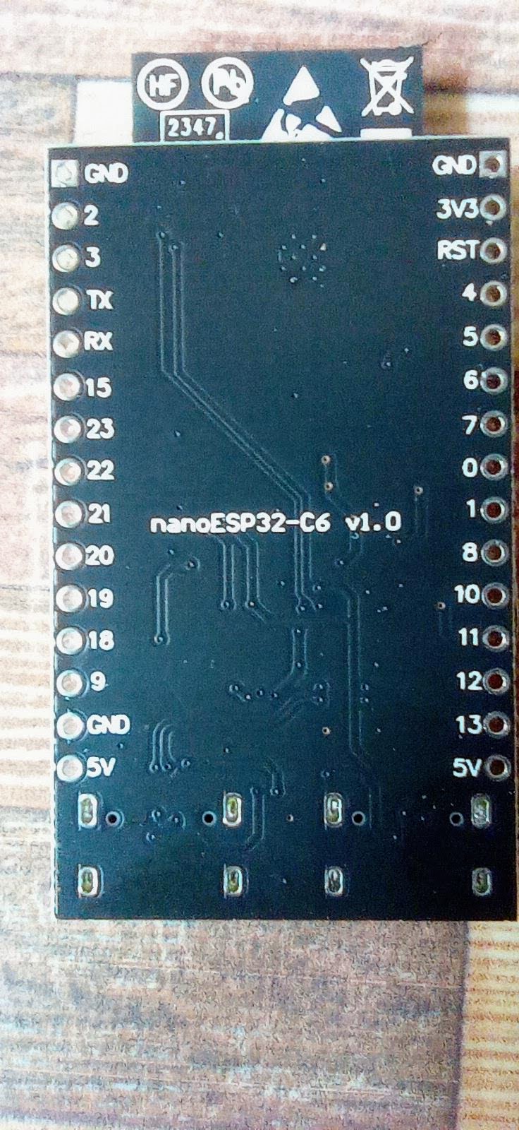
just notice: nice print 'GPIO' numbers front and back
possibly this
GIT
is from this board i have? from
MuseLab ? the original developer of that clone board ?
other source show a PINOUT:
use USB C cable and power up
RGB-LED white blink
looks like i can use both ports for upload, but see
Serial.print only when use left / CH343 port
remove USB cable
press [boot] button
connect USB cable
( that extra step was only needed for the first upload connection from Arduino IDE )
start Arduino IDE / tools /
Board: ESP32C6 Dev Module
Port: /dev/ttyACM0
* try get board info
* try RGB LED
void setup() { // put your setup code here, to run once:
 Serial.begin(9600);
 Serial.println("ESP32 C6");
#ifdef RGB_BUILTIN
 Serial.println("RGB_BUILTIN TRUE");
 Serial.println(RGB_BUILTIN);
#endif

}

void loop() { // put your main code here, to run repeatedly:
#ifdef RGB_BUILTIN
 digitalWrite(RGB_BUILTIN, HIGH); // Turn the RGB LED white
 delay(1000);
 digitalWrite(RGB_BUILTIN, LOW); // Turn the RGB LED off
 delay(1000);

 rgbLedWrite(RGB_BUILTIN, RGB_BRIGHTNESS, 0, 0); // Red
 delay(1000);
 rgbLedWrite(RGB_BUILTIN, 0, RGB_BRIGHTNESS, 0); // Green
 delay(1000);
 rgbLedWrite(RGB_BUILTIN, 0, 0, RGB_BRIGHTNESS); // Blue
 delay(1000);
 rgbLedWrite(RGB_BUILTIN, 0, 0, 0); // Off / black
 delay(1000);
#endif
}
ESP32 C6
RGB_BUILTIN TRUE
39
?39 ? i read GPIO8 ?
and a nice color BLINK show
1M loop test
my usual speed test for micro controller is
* count 1 000 000 loops // and measure the passed time
( that is not a single for loop to 1 000 000 // it must include the I/O cycle between the loop calls )
and also allow that test while add
* a 1 sec counter
* a N sec counter
* a 1 min counter
( for like a PLC type task structure )
void loop(void) {
 //loopC();
 //loopNsec();
 //loop1min();
 loopM();
}
result:
* ESP32 S3 (240MHz) and
* PICO 2W ( at 200MHz)
are 10 times faster as this
- - ESP32 C6 (160MHz)
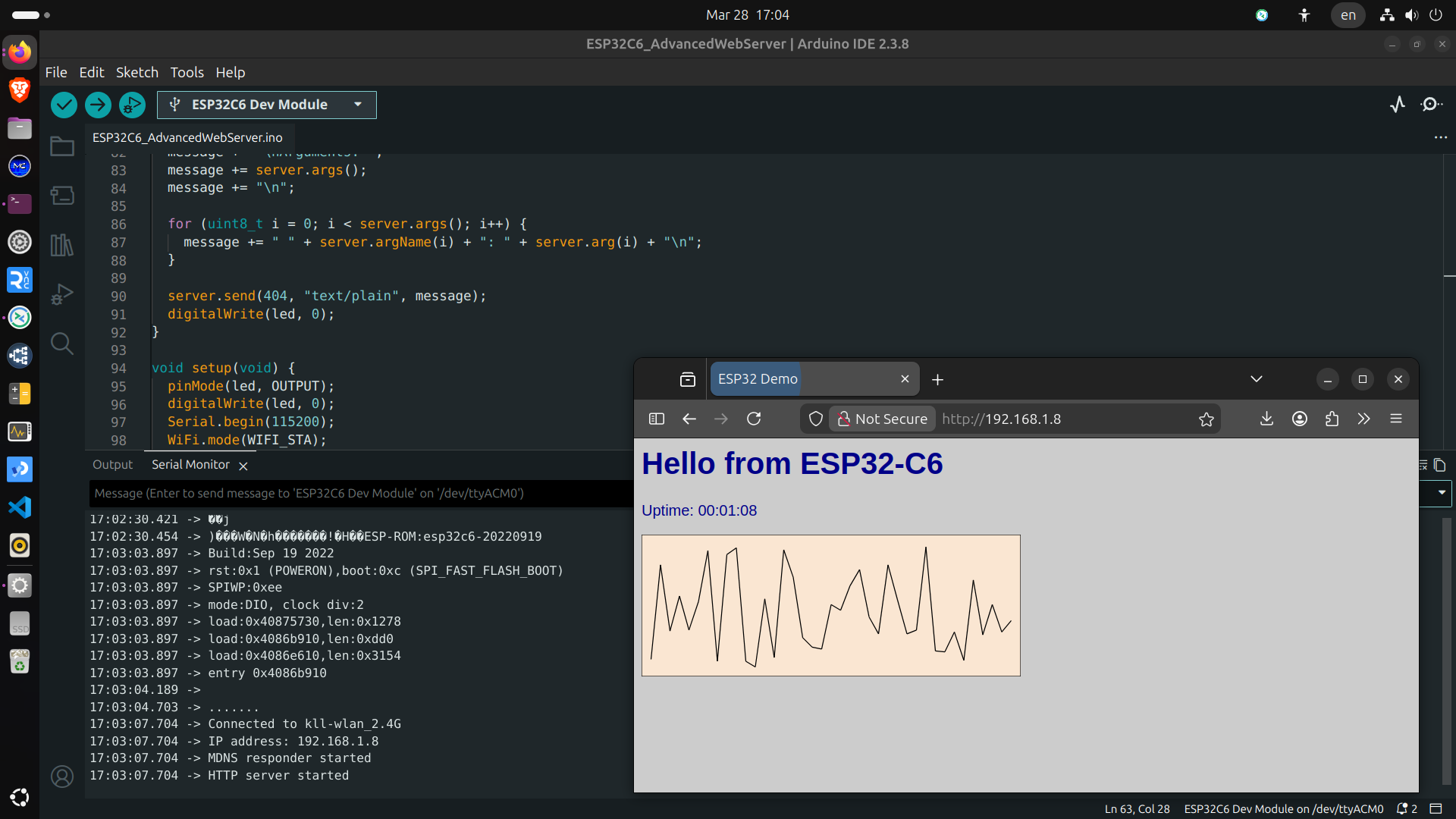
WiFi and Advanced Webserver
use the Advanced Web-server example
set wifi SSID & password
upload and find IP printed to call via browser.
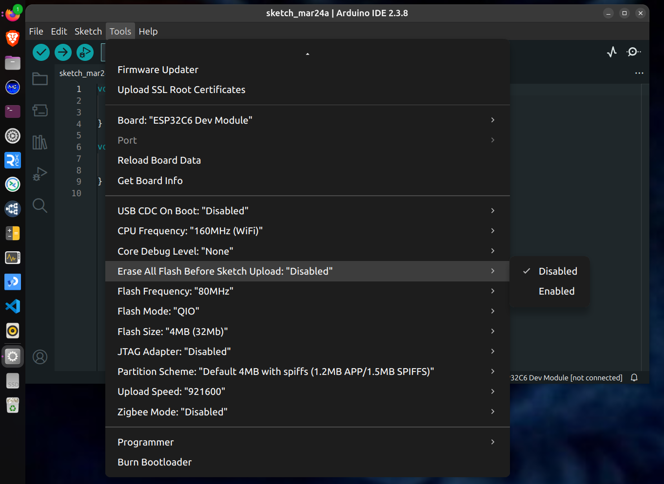
check 16MB flash
set
/Tools/Flash Size 16MB
test with this code:
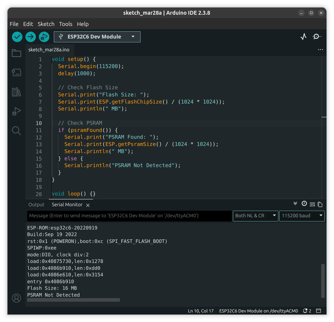
so yeah,
think i bought the real thing
for small / low power IOT projects,
even with that CPU and no PSRAM
far from the older powerhouse ESP32 S3
but with the enhanced communication
check WiFi signal
so, above i already run WiFi web-server
and at the beginning i talk about how the antenna on that boards might perform?
sure i not have any professional equipment ?meter?
but i think of prepare a easy test
ok, on my phone i have a app
WiFi Monitor
i used to check if my router can be 'seen' from the gate, because i wanted to install a WiFi security camera there.
- - and well location not good, too far and building in-between, that anyhow is a WiFi / Radio killer, build from AAC stones
i go tab NETWORKS and see ( refresh rate terrible )
* my router 8m away RSSI (Received Signal Strength Indicator)
* * 2.4G -42
* * 5G -48
so now i upload a example code: AP mode
/WiFi/WiFiAccesspoint
upload
and can walk with the phone to create distance and measure decibel-milliwatts (dBm)
if need to walk with the ESP ( like for check when the router connection breaks ) can use a USB power-bank to drive it.
RSSI (Received Signal Strength Indicator)
* * 2.4G -24 for 0.2m away
* * 2.4G -32 for 1m away
* * 2.4G -63 for 10m away
when i have the 'super-mini' i can compare the results.
Power Meter Project
now i test if it also could be used in my big pending project see last BLOG
big combi project with ESP32S3
* also use PICO 1&2 W boards
* many optional sensors INA219/260 // ACS712/758 // ADS1115
* optional 4 relay board
* MQTT TLS with local and remote Node Red
* Web-Page incl. Login and operation
because of that many BOARD and SENSOR options it is unreadable ( compiler switch ) code
let's test if it fits in this new board
as commanding that code might be, it runs on one core, not use PSRAM PSFLASH
so i used the ESP32S3 setting and upload to ESP32C6
+ WiFi login
+ NTP
+ MQTT TLS remote broker
+ web page
- - where i get a error on [LOGIN] File Not Found // URI: /login // Method: GET // Arguments: 0
check: enable
#define use4RELAY
upload
+ + login OK
( need some work and also check on 4 D-OUT for this board available )
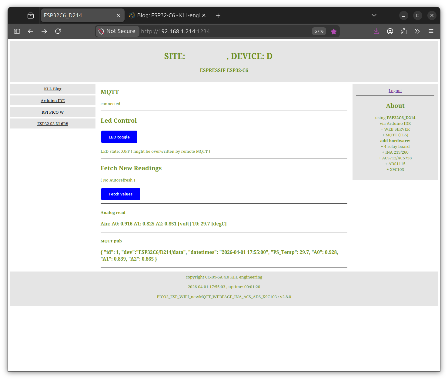
web-server on local LAN / dynamic data view ( optional operation with login )
not bad for a < 5 EUR board
+ + but the real power is in a MQTT broker connection
+ + + local Mosquitto on a RPI4
OR
+ + + optional remote ( TLS )
( i use
HIVEMQ free account )
+ + + and using a Node-Red ( with SQLite DB ) dashboard on that local OR remote connection.
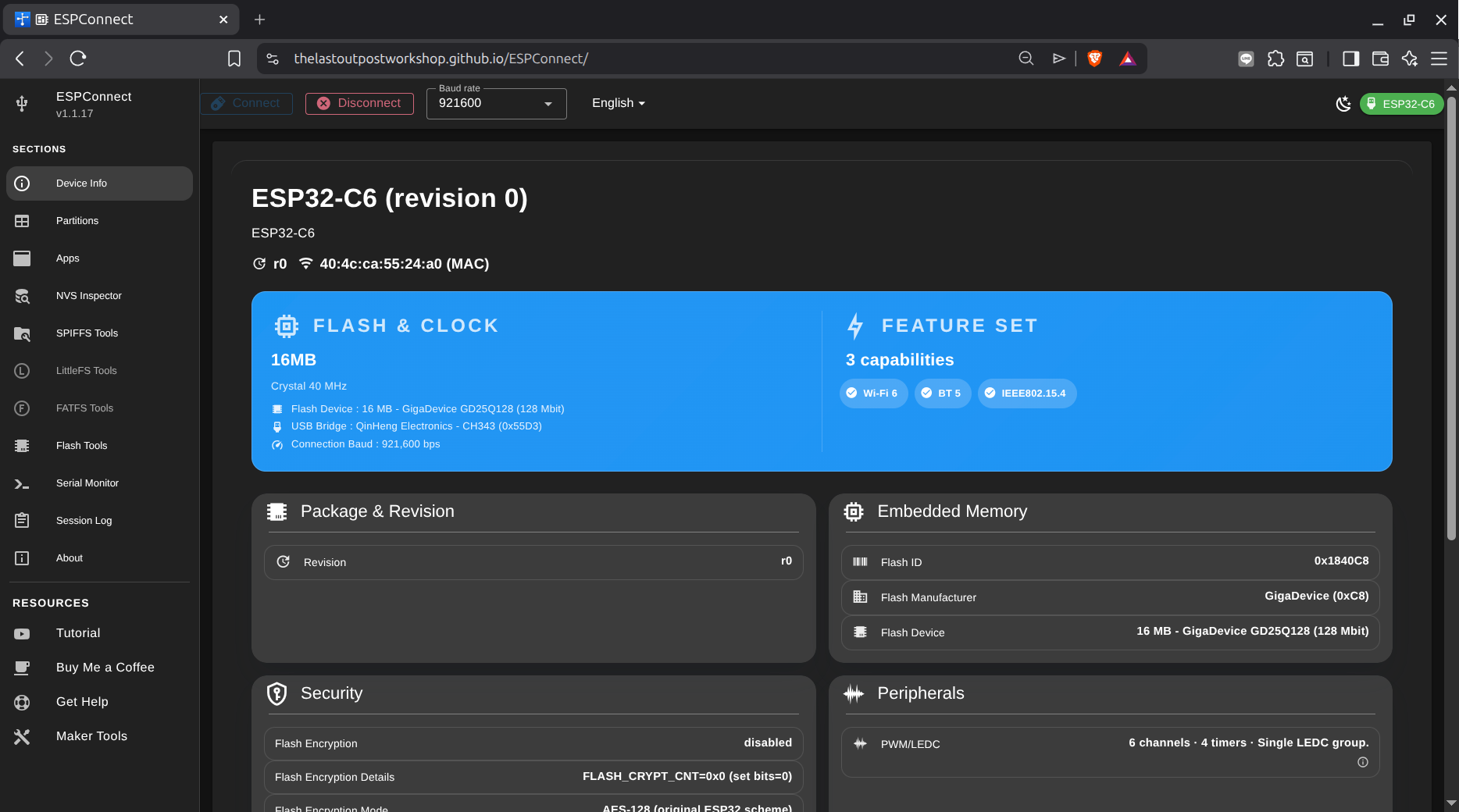
ESP connect
there is a tool ( running in a chrome/BRAVE web browser )
to check on ESP boards.
YOUTUBE original
YOUTUBE new
GIT
START
and connect the board ( here try ESP32-C6 left USB-C port "CH343" )
find the USB port ( here "USB single serial ttyACM0" )
play some tutorial
see some online tutorial worth watching:
youtube or
site
but looks like while there is the code for the Arduino IDE main file in the web page ( for each of the 4 versions )
i could not find the external code for the web-server site:
html.h
so i not play with it.