after test
INA219 and INA 260 sensor (I2C)
here
now try a
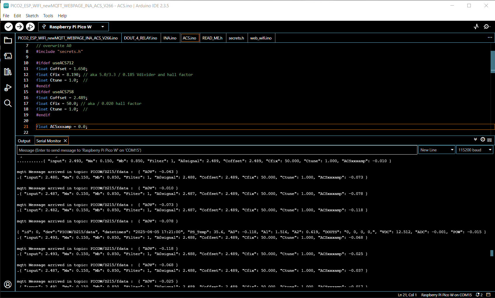
ACS712
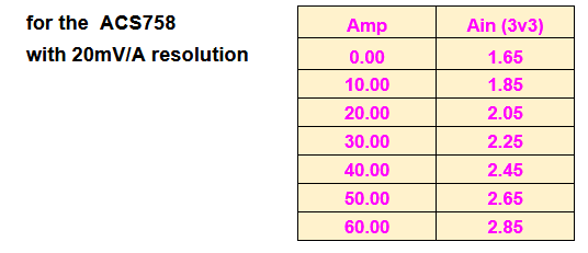
ACS758 extra
ACS712
datasheet
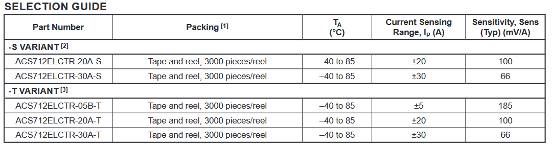
here we try the 5A version:
on a ESP32s
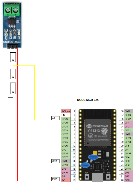
( sorry for the pure/poor SPREADSHEET circuit )
theory:
1 board is powered by 5V
2 if 0 Amp output is Vcc / 2 so: 2.5V
3 if board is 05B-T 5A range 185mV/A resolution
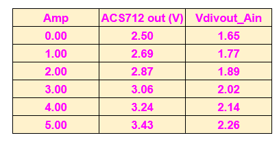
4 if read Ain in Volt 'A0V' 2.5 .. 3.425 V signal range for 0 .. 5A
A = ( A0V - 2.5 ) / 0.185
on 3v3 boards use a Voltage divider 1 kohm / 2 kohm possibly make the 2 kohm by 2 * 1kohm in series
need to correct A0V back
A0V= A0Vmeasured * 5.0 / 3.3
calibration:
for a linear calibration need 2 tuning parameter:
Coffset 0.0 in Volt
Ctune 1.0
A = ( A0Vmeasured * 5.0 / 3.3 - 2.5 + Coffset ) * Ctune / 0.185
in a first step make a new switch
#define useACS712
and in Ains() add these calculations and print the Amp every second for test
first i try just print that result from Ains() .. that's every second
then i did something BAD aka LAZY
i overwrite A0Vmeasured with that result
and it goes all the way MQTT Database... Hist Trend
means i just change the understanding of that A0V value to ACS712 AMP
problem is also that my mqtts string is full ( 2xx chars limit? )
if i want report a new thing to mqtt
i should make a extra TOPIC / PUBLISH / CURRENT TREND /
and then the real problem starts about hist database and hist trend...
but with a BAD but fast / 5 seconds / patch i avoid all that.
our ACS and the first code give us trouble to calibrate
so changed the ZERO calibration easy way
add introduced a filter code
also simulated it in
spread sheet
in V265
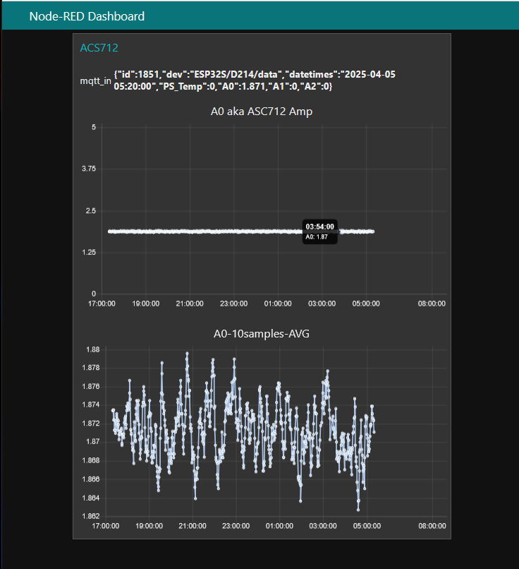
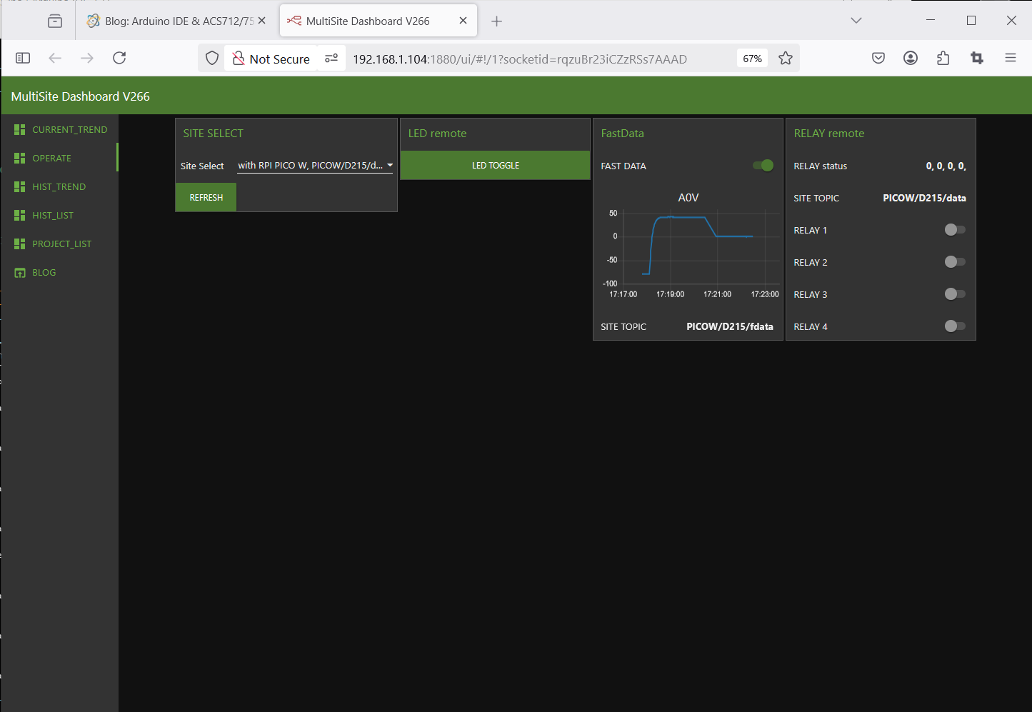
the diagnostic print ( every second ) is also send to ( local ) mqtt what easy shows a temporary trend
how to tune?
-1- enable that diagnostic print
now in v270 there are 2 official ways
to see that info:
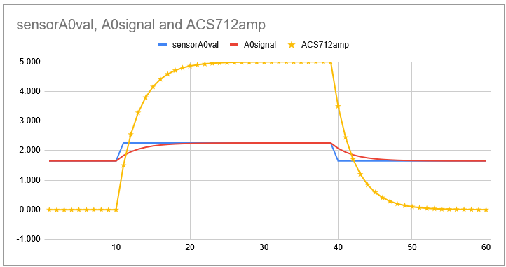
-1.1- NR operation Fast Trend
there will be a adhoc Current Trend of A0 ( what actually is the calculated Current [A] )
and add there is a print of the filter and tuning and calculation values every second
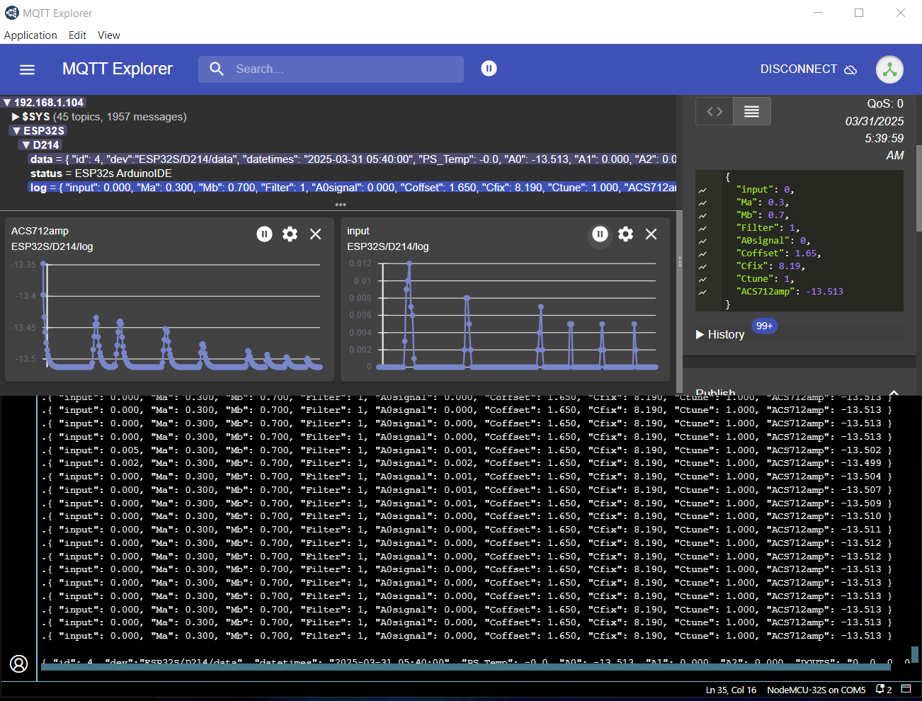
+ + in arduino terminal
++ in mqtt /log
++ even in REMOTE mqtt /log ! costs money !
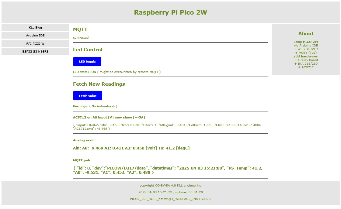
-1.2- look at the web-page of a ACS enabled device and find
ACS712 on A0 input [V] now show [+-5A]
{ "input": 0.026, "Ma": 0.150, "Mb": 0.850, "Filter": 1, "A0signal": 0.042, "Coffset": 1.650, "Cfix": 8.190, "Ctune": 1.000, "ACSxxxamp": -13.173 }
( for a esp32s with ACS712 enabled BUT not connected )
press the
[Fetch values] button for update
-2- disable or lighten the filter..
for calibration work better work without or little filter ( Ma 0.3 )
-3- at 0AMP calibrate 0.0Amp by changing Coffest to the incoming Volt you see ( about 1.65V from Voltage divider )
in that diagnostic print line "input" is the actual A0 ADC [V]
while in mqtt... A0 is the resulting / calculated [A] called "ACSxxxamp" in diag print
-4- at 2 ..5 A check amplification, that 0.185 V/A might be not too accurate, change Ctune ( from 1.0 to 1.xx ) to adjust
-5- disable diagnostic print
-6- strengthen the filter ?0.15?
short code see
ACS712_shortcode.txt
for the project code pls see
at the end
working on the next version:
-a- move the code into a
ACS.ino
-b- if use ACS show the diagnostic line also in the web-page
-c- the print diagnostic every second to arduino terminal and mqtt /log
is moved from buildswitch to variable
and can be now also toggled via the NR operation FAST TREND ( of A0 )
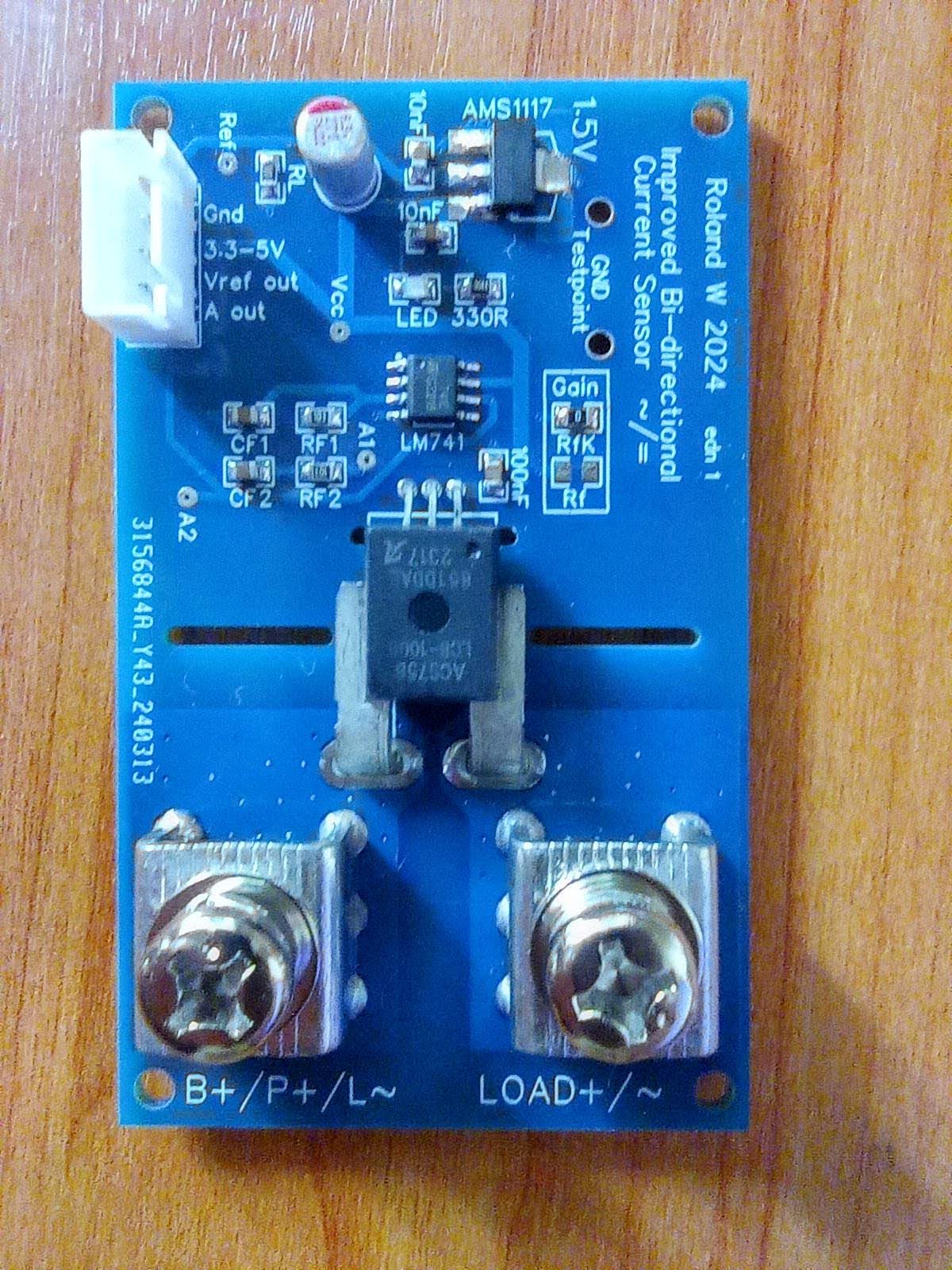
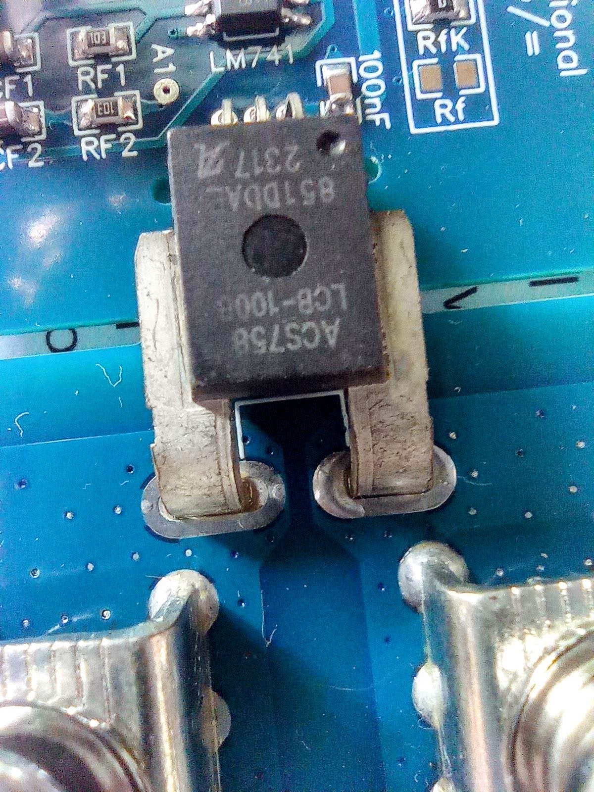
ACS758 extra
got the board from
rolandw
and he also has
GIT and
youtube
sponsored by
GCRA
the sensor is a +-100A
ACS758
this board can be used with 5V (+-85A)
or 3V3 (+-60A)
and that is what we need for ESP or PICO boards
without using a 5/3.3 Voltage divider, like needed for ACS712.
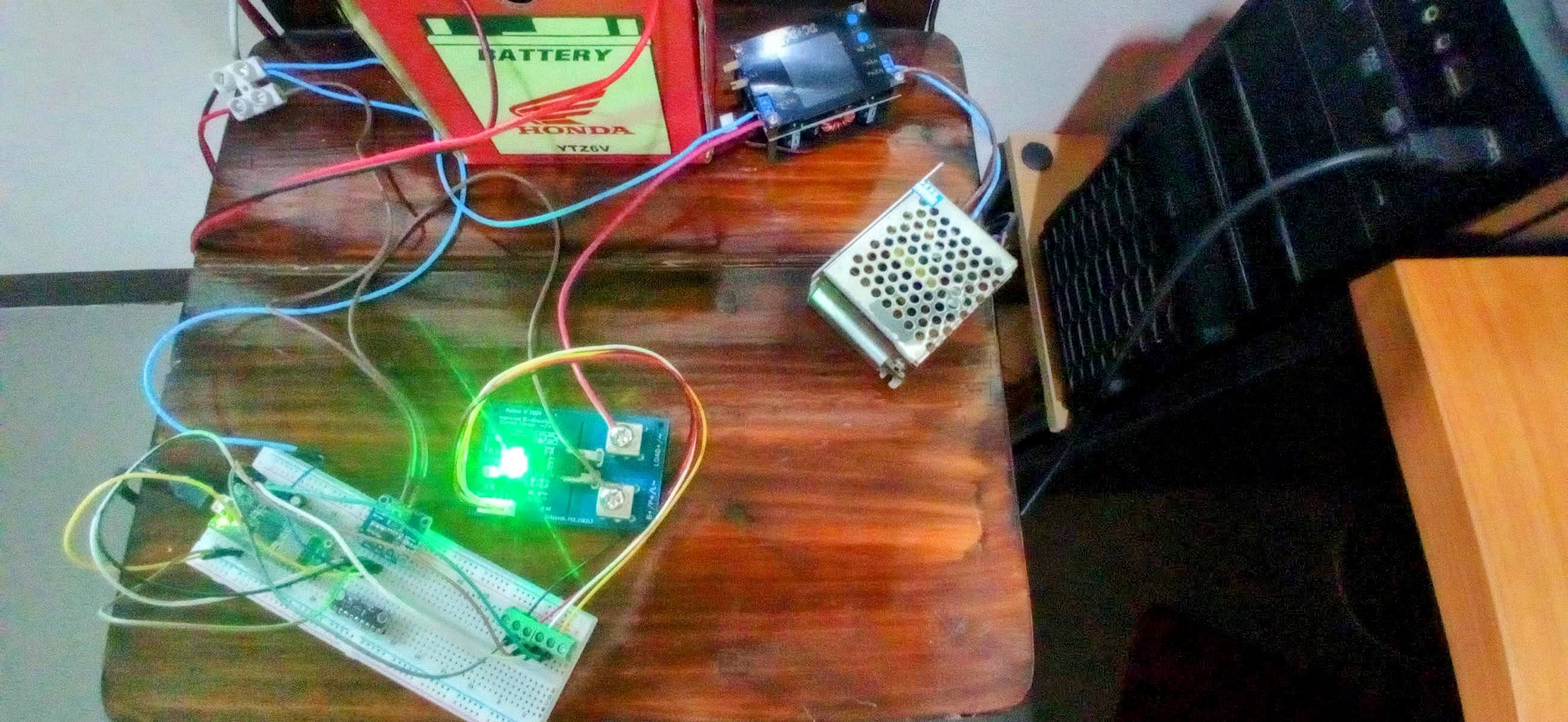
for the first hardware connection tests i use
* PICO W
with Arduino project
* PICO2_ESP_WIFI_newMQTT_WEBPAGE_INA_ACS_V266
but no serious current, all i have in that setup is the 0.5A measured by INA219 ( max 3A power-loop)
and that is on a poor breadboard setup ( PICO W / INA219 / new ACS758 )
while the 15A ACS758 / INA260 test site is setup far far away,
i start making a new #switch ACS712 or ACS758 in the code.
but bad news, looks like can not use that board on 3v3
ACS758LCB-100B ( not the '-T' version ) seems
5V only.
possible signal then might be:
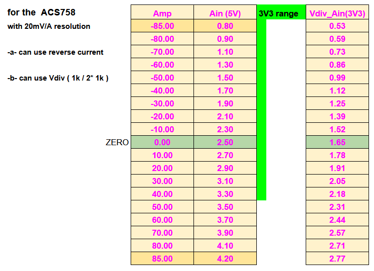
if we use that board ( on 5V ) i recommend to revert the current
( our application is uni-directional only )
and NOT use a 5V/3v3 voltage divider ( risks ? )
looks like:
-1- PS is OFF ( but battery connected see INA219 "VDC":12.508, )
-2- ACS758 power on 5V USB
-3- Coffset about 2.49 [V] adjust
-4- A0 is the ACS758 Amp ZERO
-5- see in A1 Vref 1.5x [V]
-6- adjust Cfix = -50.0 ( reverted current )
and see | power up (5V) | adjust Coffset | in FAST TREND A0
-7- later adjust Ctune = 1.0 +- x after check with 20 / 40 / 60 / 80 A