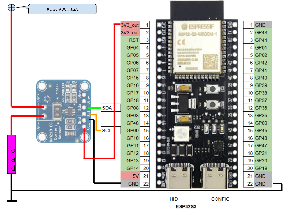
i try ESP32S3
and INA219
and failed about finding that device. actually
I THINK I BURNED MY DEVICE?
INA219 power meter
INA260
INA219 power meter
for a special job try to get data from a INA219 breakout board ( here about 1$ )
Volt / Amp / Power meter I2C connected,
* limit
* * 26 VoltDC
* * 3.2A // using a 0.1 ohm shunt on board
but before i order a new one, i will try that device again..
as it was running under
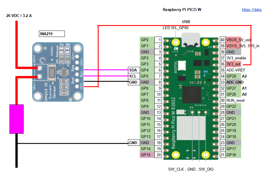
PICO W / CircuitPython /
in this
project
and
follow
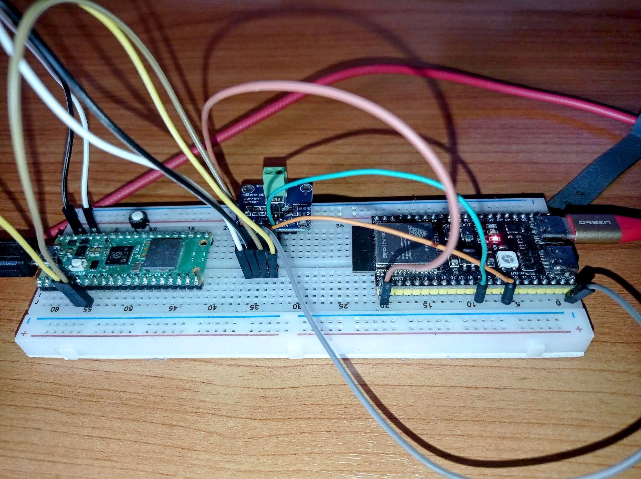
just for test use that setup to try that device again before i order new one
get from there:
PICO_W_CP800_Multi_Task_DIO_Ains_Temp_DHT_INA_ADS_USB_MENU_dynamicWebserver_MQTT_PMS1WdotPY_V1.2.3.zip
and nuke and setup CP800 and copy in code
also install MU editor on win10PC again.
enable wifi and INA
and see at boot:
___++ INA219
___++Config register:
___++ bus_voltage_range: 0x1
___++ gain: 0x3
___++ bus_adc_resolution: 0xD
___++ shunt_adc_resolution: 0xD
___++ mode: 0x7

___+ Voltage (VIN+) : 0.888 V
___+ Voltage (VIN-) : 0.888 V
___+ Shunt Voltage : -0.00005 V
___+ Shunt Current : -0.0005 A
___+ Power Calc. : -0.00044 W
___+ Power Register : 0.000 W
so as it is communicating well i have a good hardware setup ( ok, without the POWER PART wired )
just leave it as it is and start coding Arduino IDE & PICO W + INA219
using the ADAFRUIT LIB
make a switch 'useINA' ( see secrets.h )
start INA after serial init
PICO W on Arduino IDE 2.3.4
Measuring voltage, current, and power with INA219 board
Bus Voltage: 0.89 V
Shunt Voltage: 0.01 mV
Load Voltage: 0.89 V
Current: -0.10 mA
Power: 0.00 mW
i did not set any pins / GPIO to wire() or ina219.begin(),
no idea why it works on that pins on PICO W ( what i actually wired for a CircuitPython project )
// wire SDA PICO W GP4 (pin 6)
// wire SCL PICO W GP5 (pin 7)
but if you check a PICO W PINOUT
that are marked as I2C0_SDA and I2C0_SCL ( like also GP0 and GP1 ) !
but with a darker color MEANS DEFAULT PIN
so it is very clear that there is no hardware issue or general Arduino IDE thing,
ERROR must all be in my first setup with ESP32S3 and the used pins.
while here with PICO W i was JUST LUCKY ?
look what i found:
C:/Users/user/AppData/Local/Arduino15/packages/rp2040/hardware/rp2040/4.4.4/variants/rpipicow/pins_arduino.h
// Wire
#define PIN_WIRE0_SDA (4u)
#define PIN_WIRE0_SCL (5u)

#define PIN_WIRE1_SDA (26u)
#define PIN_WIRE1_SCL (27u)


C:/Users/user/AppData/Local/Arduino15/packages/esp32/hardware/esp32/3.1.3/variants/esp32s3/pins_arduino.h
static const uint8_t SDA = 8;
static const uint8_t SCL = 9;
made wire scan and INAtest code ( pls find it also in the ZIP )
and
here
also report to
forum.arduino.cc
with the new hardware setup it works now also with ESP32S3 ? was a bad cable issue ? as the above circuit drawing was correct!
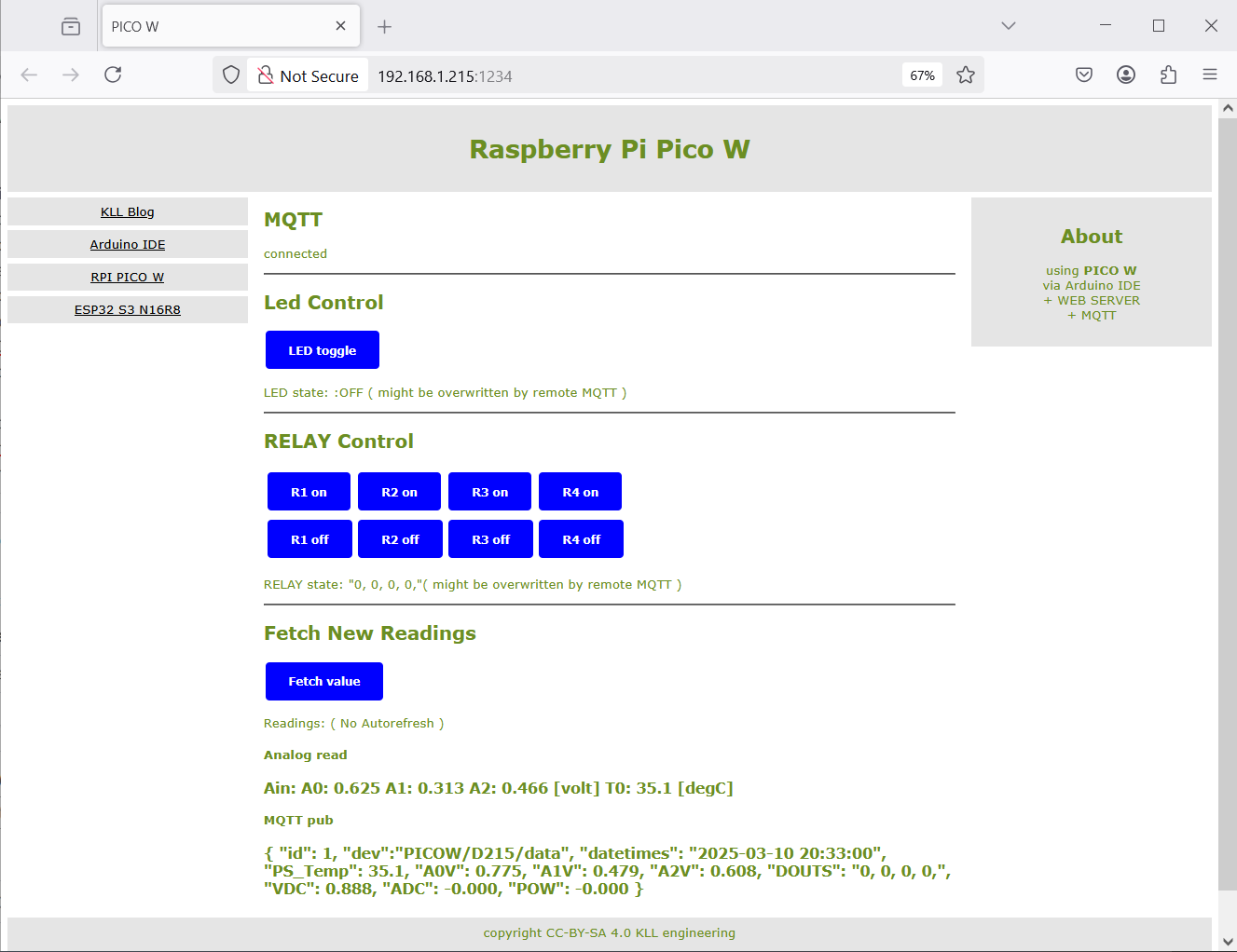
my project WEB-SERVER MQTT(TLS) 4 RELAY board and now INA219
how to use
-a- do that INA measuring every second
-b- make a global String what can be used/added inside the MQTT string ( flat structure )
so it automatically is published to broker and webpage
and easy can be used by NR
, "VDC": 26.000 , "ADC": 3.200, "POW": 55.550
like
.
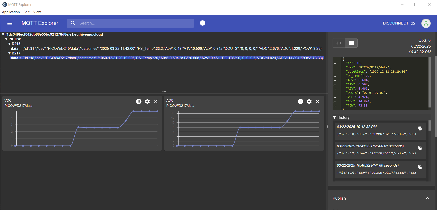
{ "id": 0, "dev":"PICOW/D215/data", "datetimes": "2025-03-10 20:32:00", "PS_Temp": 35.1, "A0V": 0.941, "A1V": 0.643, "A2V": 0.749, "DOUTS": "0, 0, 0, 0,", "VDC": 0.892, "ADC": -0.000, "POW": -0.000 }
.
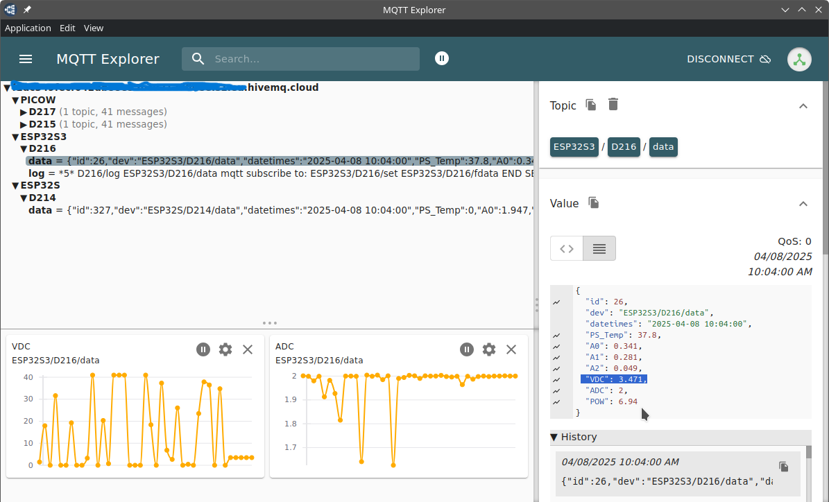
and show MQTT string also in webpage:
also i see that in local and remote broker ( NR copy )
and in NR mqtt_in string
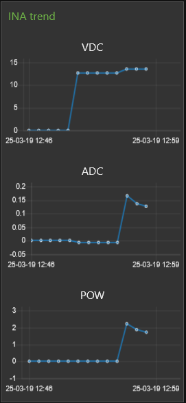
UPDATE NR: now have 3 trend groups for that INA data
combined code v2.x.x
pls find Arduino project:
PICO2_ESP_WIFI_newMQTT_WEBPAGE_INA219
and with this version the latest boot log:
ESP32S3 on Arduino IDE 2.3.4
PICO2_ESP_WIFI_newMQTT_WEBPAGE_INA219
revision: v2.5.3
Measuring voltage, current, and power with INA219 board
.
www Connected to <SSID>
www IP address: 192.168.1.216
Setup ntp...

www HTTP server started on http://192.168.1.216:1234
mqtt setup_MQTT
mqtt try connect to MQTT broker ...
mqtt broker: 192.168.1.104 connected
mqtt publish to topic: ESP32S3/D216/status
mqtt publish to topic: ESP32S3/D216/data
mqtt subscribe to: ESP32S3/D216/set
mqtt subscribe to: ESP32S3/D216/fdata
.................................
{ "id": 0, "dev":"ESP32S3/D216/data", "datetimes": "2025-03-12 11:34:00", "PS_Temp": 36.2, "A0V": 0.728, "A1V": 0.692, "A2V": 0.085, "DOUTS": "0, 0, 0, 0,", "VDC": 0.884, "ADC": -0.000, "POW": -0.000 }
..
Node-Red
from Arduino Serial Monitor you see the MQTT string printed ( every minute )
but when i check NR see ERROR
there was a String to Char-array conversion limited to 200 bytes
that cut the trailing "}"
( after change to 250 bytes all ok again.
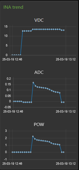
still i want see the INA data in CURRENT TREND
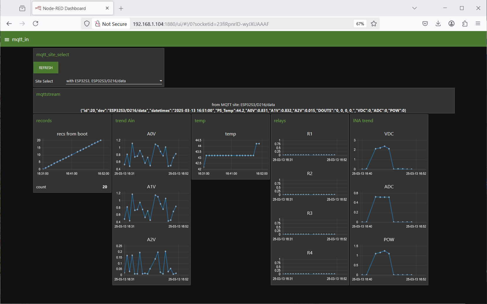
pls see the VDC / ADC / POW trend at the right
( while the full mqtt_in string is send to REMOTE broker and to DB )
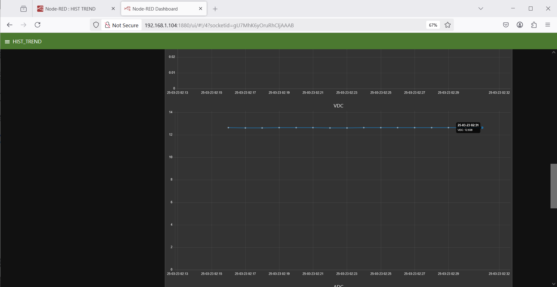
OLD:
but there is NO HIST TREND of INA data provided.
UPDATE:
there are 2 flows to work on in actually 3 easy steps
-a- SAVEtoDB database design change
no need to delete the DB file ( as it also has the project database )
press [delete table]
press [create table] ( adds the INA columns )
-b- SAVEtoDB select values for new columns and store
-c- HIST-TREND add 3 data select and trends
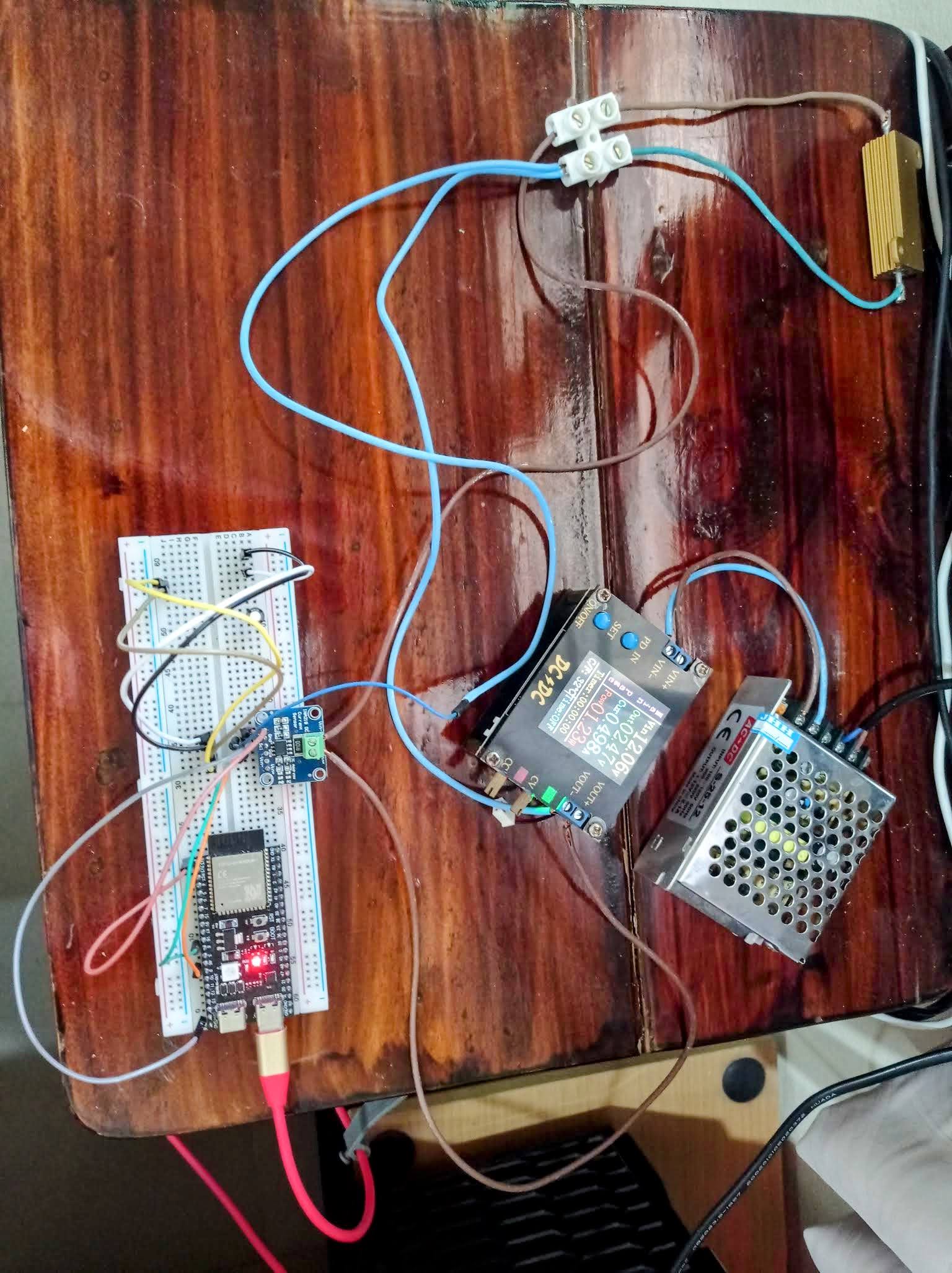
Power Loop
i not have much tools here, but i am thinking of a 12V Battery charger circuit.
as i not have one i try to build a small one
-a- a 12DC 2.1A power module ( for now )
-b- a DC / DC module with current limiter / Buck-Boost CV CC ( 1 .. 30V 4A with display and fan )
-c- a load resistor or old motorbike battery 12V
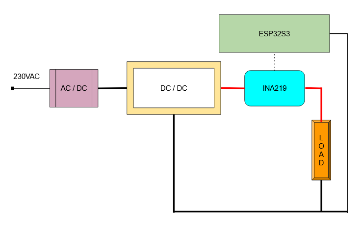
pls. note, there are 3 wires to the "power circuit"
but only 2 screw connectors on this board, the boards with add ground screw connector are rare.
ESP32S3/D216/status ESP32S3 ArduinoIDE
ESP32S3/D216/data { "id": 0, "dev":"ESP32S3/D216/data", "datetimes": "2025-03-13 12:37:00", "PS_Temp": 34.2, "A0V": 1.176, "A1V": 1.235, "A2V": 0.295, "DOUTS": "0, 0, 0, 0,", "VDC": 2.416, "ADC": 0.522, "POW": 1.261 }
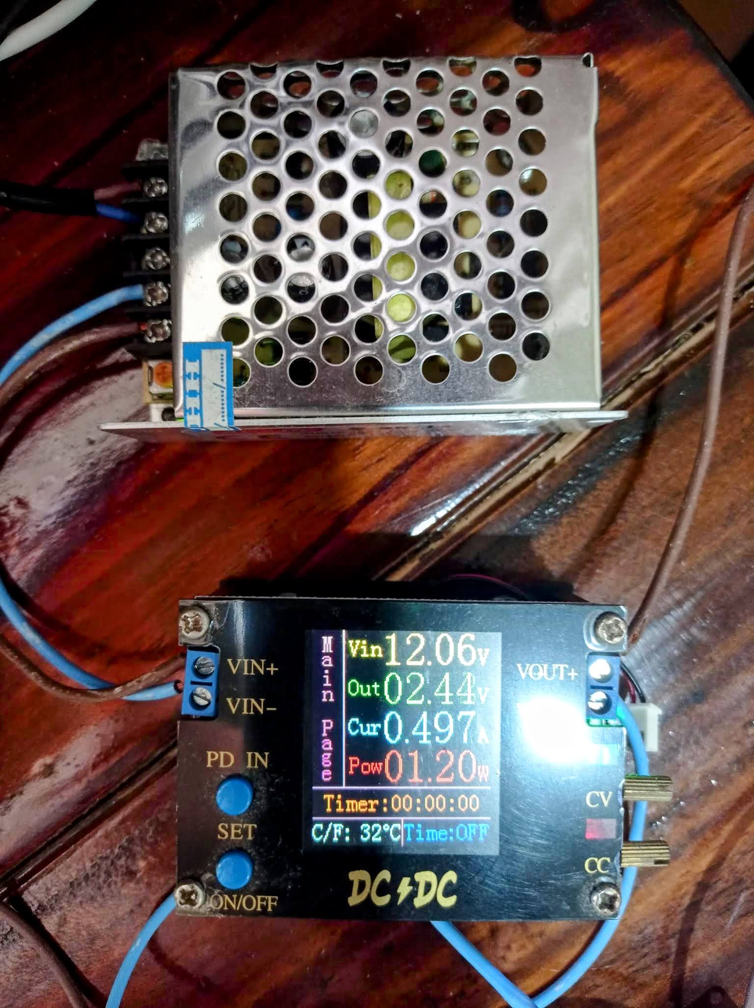
INA measurement:
"VDC": 2.416, "ADC": 0.522, "POW": 1.261 comes close to the DC/DC indication.
the Power Resistor got HOT ( even i throttled the current to 0.5A ) so can not run long time.
 pls. note
that circuit is not galvanic isolated, so the 12VDC GND is connected to ESP32S3 GND
and in this case still USB to PC ( to print the diagnostic prints )
PC (USB) GND is connected too.
later ( in production ) no PC connected, the ESP has its own charger ( USB 5V ?2A)
that also limits the $$$ that can burn down.
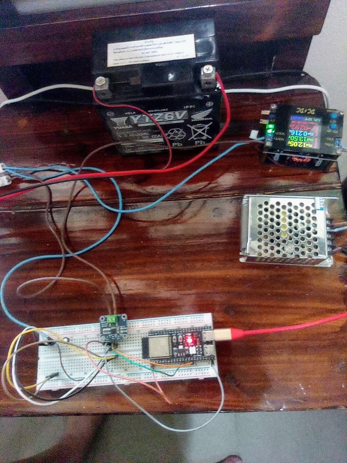
now let's try how it works with a 12V battery as LOAD.
the old one i have should be EMPTY to DAMAGED? will see.
"YTZ6V" is a very funny name for a original HONDA 12V 5.3Ah battery
and it states the charging is 0.5A for 10h ( or quick max 2.5A )
i not know at what Volt you should charge a lead acid battery ? max 14.xxV ?
but if i limit the current 0.5A AND the volt to lets say 13.5V max it should be save.
but when i connect the 13.5V ( and measured it over the Battery terminals ) NO CURRENT
sorry, not a good show today
UPDATE 2025-03-19:
another day another old battery
my HONDA PCX 150i needed a new one / all was ok, only the auto stop start function does not work when battery voltage is weak.
( like at winter and not much driving.. OR battery just old. )
using the old battery and setting up same power loop again, same setting
* max 0.5A
* max 13.5V
and hope get a interesting charging trend on
NR CURRENT TREND
the first test worked ? little bit?...
when i connect the battery i get 12.7 VDC
( and i see that exact number at the HONDA shop battery tester when they declared it a BAD battery for my PCX )
when i start my battery charger then i see the 13.5 VDC ( adjusted V-max ) and charging start with 0.5A (adjusted I-lim) for a second
but very fast go down as that
13.5 VDC is too low.
when i stop the charger see that battery was CHARGED little bit 13.1 VDC
so have to learn more about LEAD Battery charging
with what Volt charging to get save charged Volt?
but yes, that circuit is a good Battery monitor too,
so what i need is to be able to power ON OFF the charger ( by RELAY )
and check charging progress?
or also something like a DAILY charging cycle? how to do that?
AUTOMATION in Node Red?
more to come....
INA260
while i was thinking how to get a power test-site
and how to start working INA219 with added SHUNT for higher current
a friend found
INA260
"+36V / up to 15A Continuous on either the high or low side"
( and we found the adafruit lib for it )
first i make a new arduino project
PICO2_ESP_WIFI_newMQTT_WEBPAGE_INA
and in there is a
INA.ino
and depending on a switch in 'secrets.h'
//#define use_INA_219
#define use_INA_260
INAxxx is setup and measured every second and a partial MQTT string prepared.
if initial INA connection failed use
MQTTina = ", "VDC": -0.007, "ADC": -0.007, "POW": -0.007";
every minute the full MQTT string is send to broker, about 200 char what seems also to be the limit of pubsubclient? MQTT 3?
because lib different and actually can not know if getting data, check in
current: if -0.007 it is NOT a measurement!
my friend got the INA260 powered
R = U /I as 0.329 OHM
by a electronic load
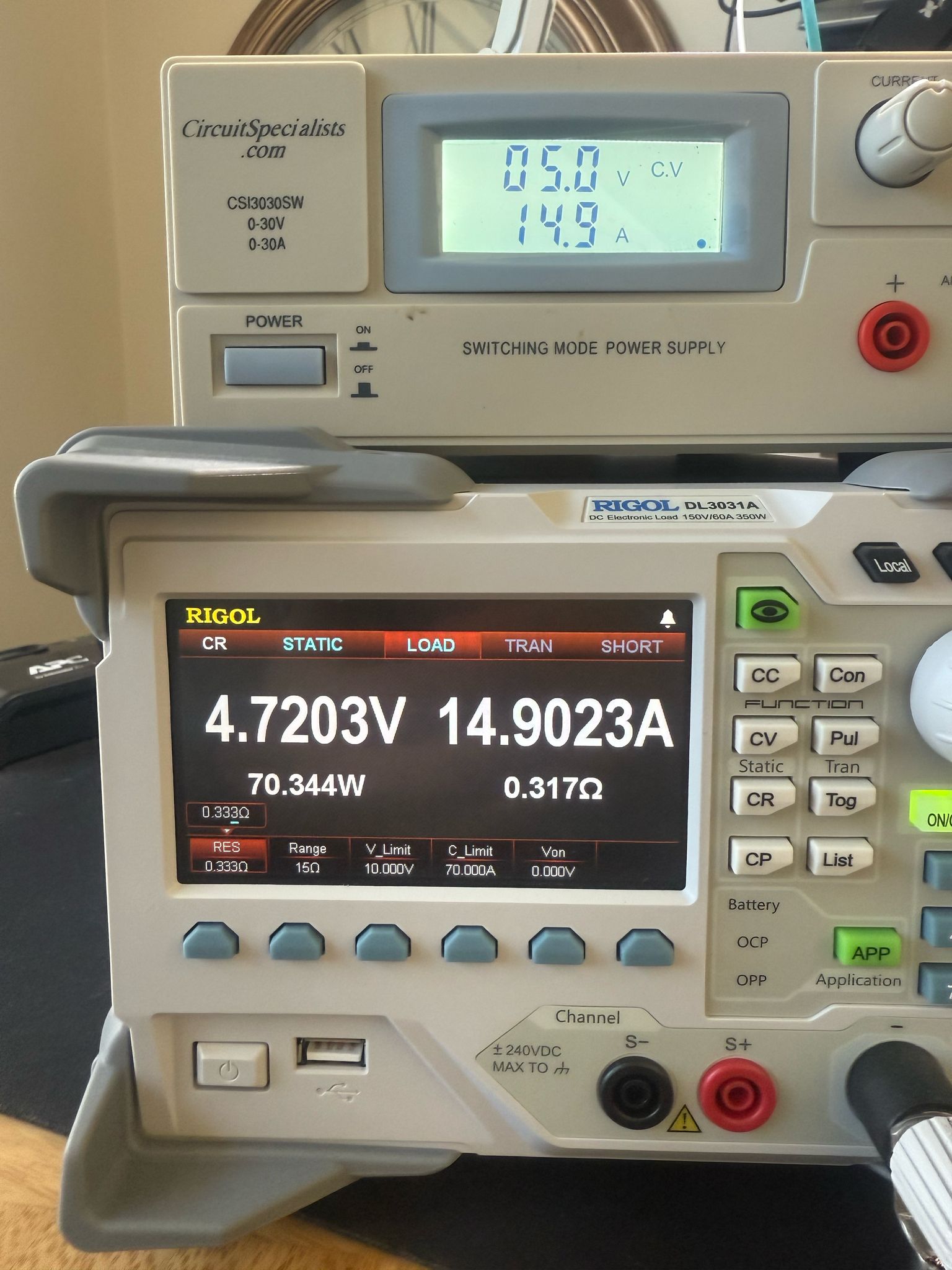
on a add new setup
*
ESP32S3( the new 'V' series original ESP hardware
ESP32-S3-DevKitC-1-N32R8V )
* new soldered INA260
* existing power_loop run 2A
forget to pull the 3rd wire ( uP GND to power-loop MINUS ) so the Volt reading can not work! LOL