RPI operates ARDUINO PID control
72 RPI operates ARDUINO PID control
the real world or as TONY STARK say
with the software and also already with
- input one wire temperature sensor DALLAS DS18S20 ( 100THB)
- output to servo Tower Pro SG91R ( 90THB)
i follow my friends idea for his PIZZA dough temperature control
but i not fully understand what / how he want to control,
i need a fast and easy test setup now.
as the PV is the temperature sensor my idea is to use a old light bulb as a heater.
influence by distance easy adjustable ( a hardware control by dimmer / even operate that by servo would be possible too )
but i have a idea that the servo has to operate a HEAT FLOW VALVE
means a something in between the bulb light irradiance and the sensor,
but not in form of a FLAP ( open close ) what might give / need a 2 point controller,
it should have a nice analog / linear control function ( over the 0 .. 100% control output )
( and it should not cost anything!! )
So back to arduino IDE ( on PC, manual operation enabled ) rev 4.05
first i must state that there is a break in the logic of the operation concept, compared to a PCS:
there is a operator on a computer screen and in
- MAN he can change the OUTPUT
- AUTO he can change SETPOINT
- CAS / RSP he can operate only the upper / cascaded loop
- - he can change the MODE..
now here is it different because i designed a hardware input for a POTI to the SETPOINT in AUTO mode.
a local operation possibility ( without any USB connected )
that requires that at boot arduino PID goes in AUTO mode. ( code setting )
but there is no local mode switch and no OUTPUT setpoint input designed.
what should be there is a hardware input of a THH over temperature switch what sets the control to interlock mode == OUTPUT 0
( but as a arduino would never be considered as safety controller ( with tripple redundant cpu...)
actually that THH would be only indicated ( by its second contact output ) and has its own hardware to the ON/OFF switch for the HEATER.
circuit
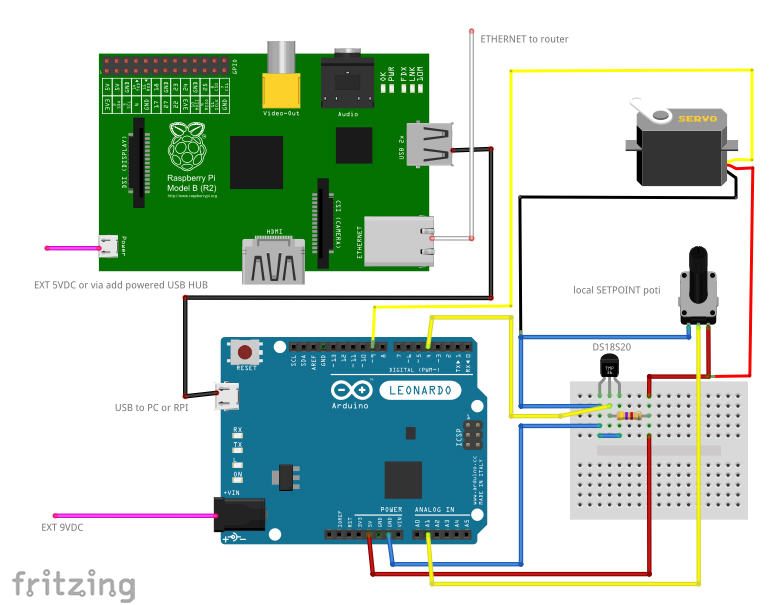
using the 5VDC generated by arduino from 9VDC might be not enough for a servo, possible reboots of arduino ...
pls check the mA consumed by servo when
- in position < 20mA
- moving 70mA metal gear, 130mA plastic gear ( no mechanic load!! )
- check with your LOAD !
- in end position with problems in the setup myservo.attach(9,400,2100); or its a bad servo, i see near 400mA and gets hot and hums.
external 5 .. 6 VDC supply for servo are better, and you might not need more hardware, because in that case might not need the 9VDC to arduino as RPI could power it ( and poti and dallas >
now to the shadow control
first some new wires,
like the DALLAS should have a 2 or 3 wire flexible cable ( anyway better buy the food grade steel capsuled version ) but i think a PID control would be a fix setup, and i could not find a audio cable shop nearby, so i ended up again with a 4 wire telephone cable for 5m / 40THB / 1 euro.
i use black to left and right pin, red to resistor soldered near sensor head, yellow other side of resistor and middle pin.
the servo has a 25cm 3 wire flex cable with a plug, the pins from the breadboard wires fit.
the poti also needs 3 wires ( from a BOX front?? ) but as i not have a 5 .. 10 kohm poti for box installation now i use the breadboard again.
i do not need that setpoint for the test, just without it the setpoint in manual mode looks so ugly from the open Ain1.
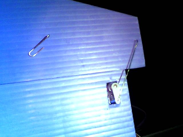
for the heat control valve i use a plastic board, cut a triangle off, and use that as movable part.
some paperclip steel as axis and actuator from servo
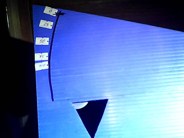
a position indication 0 .. 25..50..75..100 shows that the rotation servo / axis 1to2 / and servo position not give a fully linear valve position.
the hole in the main board ( the "seat" i made a small triangle hoping for a linearization effect )
lets the heat / light to the sensor,
the "disk" is the turnable cut of part, closes the hole at position 100%
so it must be called a "increase to close" valve or N.O. Normally Open valve.
but there is no fail position with a servo ( and no spring ) so its not a F.O. Failure Open valve.
later in the tuning we will talk about that again.
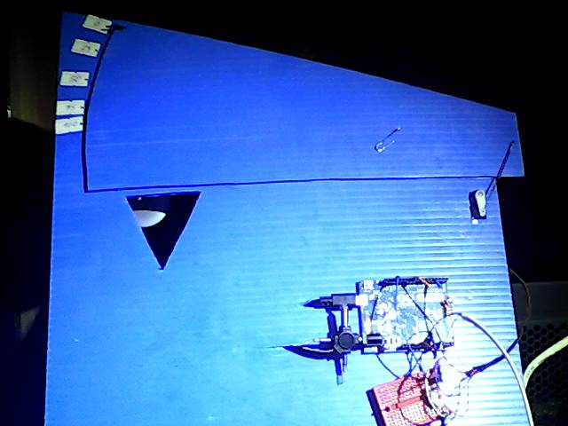


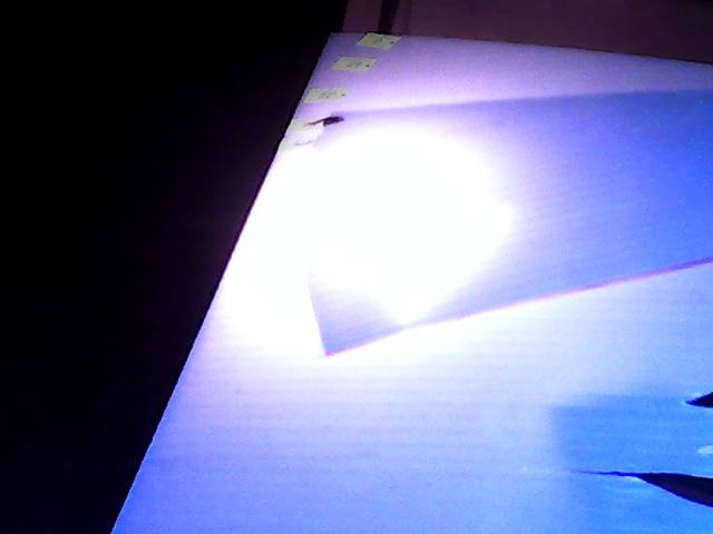
ok, the lamp is too strong and shines through the plastic ( my valve seat leaks! )
but mostly its a IR effect from my USB camera i know already,
more after the temp. sensor is installed.
( following test i made with arduino leonardo, windows 7 desktop PC )
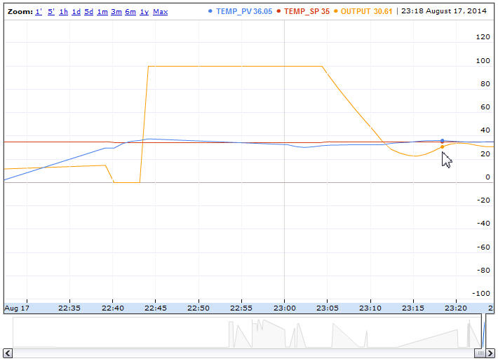
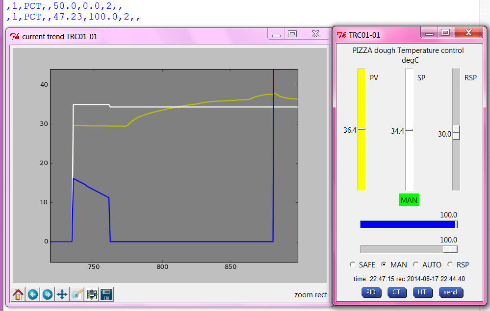
Here the first MAN and RSP test, already made the first tuning step, increase RESET , its still very slow but the trend is good. ( and not only from the data, that python mat-plot-lib tool is fantastic, for the below snaps i used the build in rectangle zoom function of that windows! )
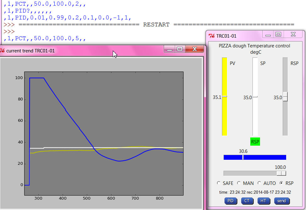
how you interpret? In RSP the PID control could catch the SETPOINT, but the PV ( temperature ) swing at first over the SETPOINT about 1 degC, see also google historic trend