
Arduino - RPI - google + RPI - Arduino operation
71 Arduino - RPI - google + RPI - Arduino operation
prior info
we did fill a google macro spreadsheet with lines by a browser call.
then we did same from a RPI with a python service after catching Arduino data from USB
now the arduino USB is blocked by that service, still we need to operate the Arduino from there too!
now we have ? a data logger ?
if the project is about a PID control ( closed loop control )
there might be need for OPERATION (HMI), minimum
- a MAN / AUTO (RSP) switch
- a input for the loop OUTPUT in MAN mode
- a input for the loop SETPOINT in RSP mode ( input for SETPOINT in AUTO by poti )
* could be done by hardware I/O, potis and one switch
* or by a touch screen interface ( a MEGA with touchscreen connected TTY serial to "control" arduino
* or via USB to "control" arduino from RPI / PC / WEB...
and here we have the problem that we can not talk from RPI with Arduino
while the python logging service is running, because the USB is in use / blocked.
So, that last service program must do that talking too.
in my RPI PoorManScope PMS3 python version i did exactly that already,
-python1- a graphical interface shows the measuring data in a graph from a datafile
and has operation buttons, these events are stored in a command file
-python2- a service read the command file and sends it to arduino
and catch the data ( blocks of 360 lines ) and stores it to datafile.
this expects that the arduino is running a menu program / is operational via USB.
there will be 2 more files,
a initial setting file
sudo nano /home/pi/arduinoproject/arduinostream_init
the service must look at startup for it
and a file made from the operation program in RAM DISK
the service must look if it exists and send its commands to USB.
i use same naming as in PMS3,
sudo nano /run/shm/arduinomenu.txt
,,10.0,50.0,5,, // notext,noPV,10 RSP, 50 MOUT, 5 RSP mode,,
that one will be overwritten after commands send to arduino by a line with one space only
( so the service know that nothing more is to be send )
pending: the operation program to write that file.
more changes to the service:
now the creation of the one-record file in ramdisk
goes with every line send by arduino, ( timing from inside arduino 5sec, but control loop cycle 2 sec )
the 30sec timer is used for google ( or csv db file on SD card ) and changed now to 60sec.
PID in ARDUINO UNO/Leonardo
my first test to copy my PID loop from uPCS ( DUE) to a UNO failed
exceeding RAM and ROM by 50%
now i try again, reducing functionality like delete tuning and back documentation,
replace lots of variables ( like for tuning ) to #define compiler placeholders
still not sure of the differences between
const float PI = 3.14159;
and
#define PI 3.14159
regarding RAM and ROM.
but i tested here, seems not to matter at all.
but still it contains many features the usual PID codes miss,
- low / high output limit
- anti reset windup limit
- ID tuning uses the loop cycle time so the tuning is independent from it.
- safe modes 0=safe, 1=interlock
2=MAN
3=AUTO, ( 4=CAS disabled because no masterloop will fit in UNO ), 5=RSP
- tracking
and accidently i found a compiler thing in arduino IDE, what possibly is a change??
i was used to need to configure the variables on the first ( main ) page / TAB
now i made the void PIDIO() as a procedure in a new TAB PIDloop.ino
and put all variables on top of that TAB, still having that variables as globals.
now for writing / and reading of that procedure that is very convenient
but on the bad side, if you use that global variables in a other TAB ( at reporting ... ), that's why they are made as globals,
you might have problems to find their definitions / settings.
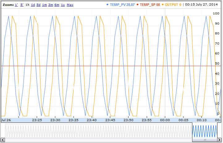
still with simulated PV sinus but testing the INIT file at power up
with RSP 50, and mode 5 RSP the controller runs / ARWU is a little bit unsymetric
need some better limit calc for the low range.
now i want follow my friend design for his control hardware:
first we need a PV:
a temperature sensor type ONE WIRE DALLAS DS 18x20 info and library measures Temperatures from -55°C to +100°C and works with 3V ..5.5V to pin2 via a 4.7kohm resistor. COM 1 AND Vdd 3 connected to COM! see also here
pin 2 DQ i connect to D4. ( see library )
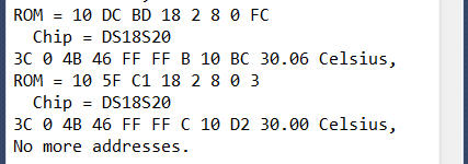
usind the DS18x20_temperature example i see:
ROM = 10 DC BD 18 2 8 0 FC
Chip = DS18S20
Data = 1 38 0 4B 46 FF FF B 10 A9 CRC=A9
Temperature = 28.06 Celsius, 82.51 Fahrenheit
No more addresses.
using 2 DS18S20 parallel see
now i just need to reduce this code to the mere reading of temperature, and do it in a new TAB ( incl all variable and lib declaration )
so i just need to write read_DALLAS(); and copy in the TAB file "DS18S20.ino".
but the PID works only in %,
for DALLAS we map like this
map(int(DStemp*100.0),-5500,12500,0,10000)/100.0 // make %
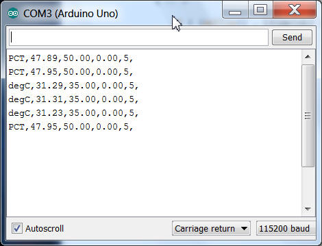
for the print / what usually also is in % ( sometimes called highway percent ) for transport to visualization system ( what needs to know the loop EGU ( PV low, high, units))
i want here have the option, a new menu entry "E" allow you to select between PCT and degC:
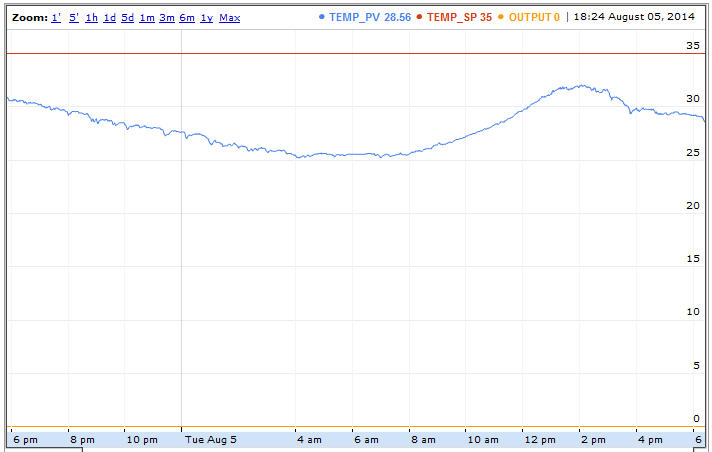
now here a 1 day ( 30sec) data collection temperature ( at my desk in thailand / raining season )
dallas, arduino, RPI, google, null problemo.
and for the OUTPUT?
now, a Arduino UNO.. has no analog output,
but PWM comes close to that for some applications.
The Arduino DUE has 2 analog outputs ( and is much bigger in RAM, ROM...)
so i use that for my uPCS ( with 2 PID, 2 IND, 2 DCD loops points examples) see also here
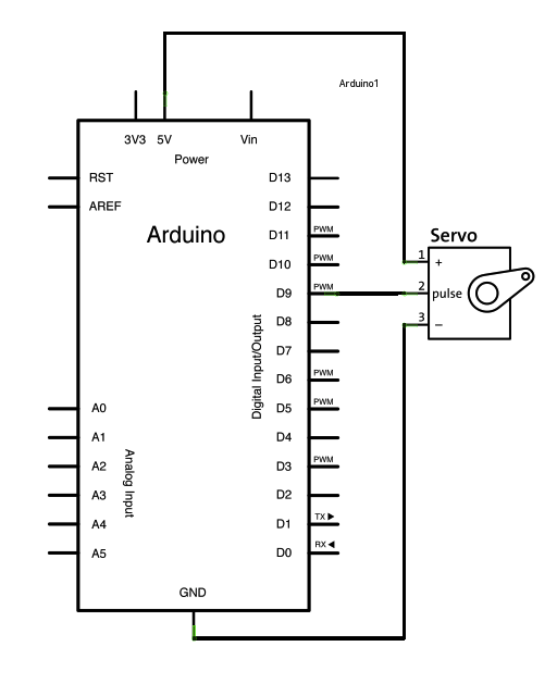
but also a Dout to a SERVO is a perfect analog output ( mechanical instead electrical ),
and it already contains the motor driver hardware, see also here, connections
i had some problem with the servo i got, so i limit its range from 20 .. 160 instead of 0 .. 180.
and a kind of strange setup i found for it in internet, possibly wrong info or type:
myservo.attach(9,400,2400); // attaches the servo on pin 9 to the servo object 400 2400
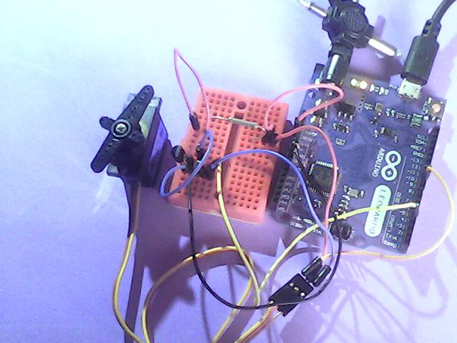
for the hardware:
looks like my USB can power arduino UNO with servo,
but for arduino leonardo need alread external (9VDC) powersupply
i think now i have a preliminary arduino setup .
next step