
ARDUINO uPCS
65 ARDUINO uPCS
in the RPI forum i find a good info about how to work from PC on RPI:
- you can open 2 putty windows (ok)
- with notepad ++ can edit RPI files directly via SSH SFTP, a very good tool if you work headless, for python must adjust some things for "new files", and for edit:
/ settings / preferences / TAB settings / [python] or [replace by space] or you have indentation errors.
also with the PC IDLE problems, options configure IDLE tab, [ok], i must do everytime i use it?
looks like i have to cleanup my code first, best way still is to develop on RPI and copy the linux files back to PC.
use a downloaded DUE on RPI is no problem, but on arduino IDE on RPI ( rev 1.0.1 ) there is no arduino DUE,
so no download from RPI to DUE possible, i will test a download to a arduino MEGA now
-1- arduinostream2-service STOP
-2-1- arduino IDE select uPCS2
-2-2- arduino IDE select board "arduino MEGA 2560"
-2-3- arduino IDE check port
-2-4- arduino IDE upload ( first try timeout, second try ok )
-2-5- arduino IDE serial monitor ( see stream ) EXIT
-3- arduinostream2-service START
-4- check ramdisk files up to date
-5-1- start arduino2operation
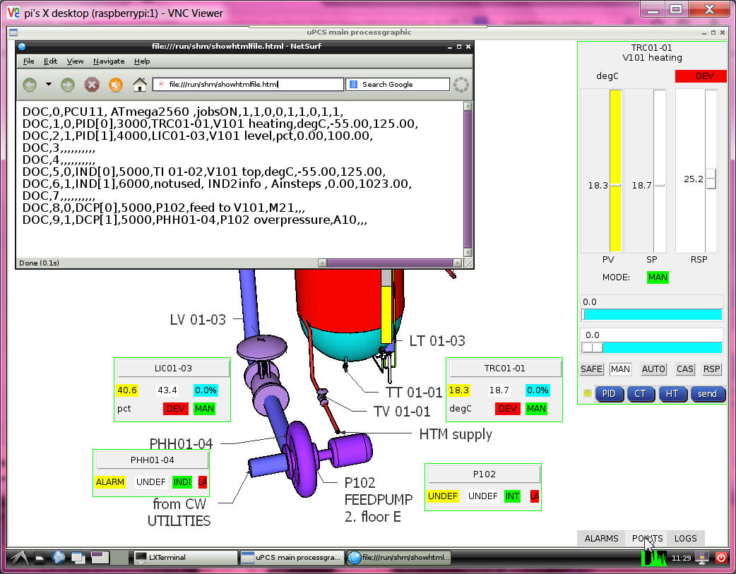
-5-2- check new button [POINTS] in processgraphic ( and note the CPU info in first line: ATMAGE2560 )
still see a small wrong bordercolor about the sliders and smaller charactersize
in the new version i define a font with size, but still different in 2 PC and RPI
anyhow i prepare the automatic selection depending on OS.
much more to do!
- hardware integration DALLAS as optional I/O
i take the code and hardware DS18B20 with 3 wire and internal 4.7k "pullup" ( its a charge resistor )
from the UNO PID project, build in more diagnostic and find a double error in that code:
- the temperature shown was always 2 times the same value, because the code was in mode device search,
found one, show value, search for more, not find, but not reset that value, show same value again.
- and in the uPCS project first use MEGA hardware, i got LOOP TOO LATE after the DALLAS call. ( changed that time warning to 1sec )
now i changed the config, if PID PV channel / IND PV channel == -2
i expect a DALLAS device addr. like my DS18B20: 28 E2 83 3E 4 0 0 1F
if the DALLAS code is called and a device addr. is provided, it not search, it calls that device and is so a little bit faster.
but if i use the DS18B20 with 12 bit still need that wait 1 sec ( > 750ms )
in "boolean dallasdiag = false; " can select that detailed diagnostic. for your device need to find that addr. info first.
add i have a test in JOB4, pls set temporary "boolean exec4conti = true; " and find in terminal window
checkinbytearray 0 0 0 0 0 0 0 0 val 0
search
ROM = 28 E2 83 3E 4 0 0 1F
Chip = DS18B20
A9 1 4B 46 7F FF 7 10 85
type_s 0
cfg: 60
12 bit resolution
degC 26.56
,4,DEGC,26.56,,,,,,
.....
checkinbytearray 0 0 0 0 0 0 0 0 val 0
search
No more addresses.
,4,DEGC,-100.00,,,,,,
now use that ROM info to configure your PID[x].PVaddr[0..7] / IND[x].PVaddr[0..7]
( the uPCS ( on USB ) not show degC usually, only PCT )
and tests with DUE ( 4um )
now change over to DUE board and connect DALLAS "pullup" to V3.3,data(2) to D4, COM(1)(3) to GND,
hope, that sensor works with that volt, that lib works for DUE..
- compile upload ok, DALLAS sensor read ok, but even with 2000 get too late warnings??
i must find a other way as that delay(1000) inside the DALLAS CODE, arduino has better things to do as to sleep and wait for slow sensors. i have a good timer ( the JOB timer ) and what i need for DALLAS would be that 1sec prior to the loop time PV read, i start the sampling already.
other way would be to start the sampling directly after the last read and run the loop every second. fast but unclean
very tricky i do the dallas things now in the contijobs
and call read_DALLAS(int modesel=0) { // 0 do all( measure, wait, getdata), 1 do measure, 2 do get data
read_DALLAS(1) about 1 sec prior to the loop JOB
read_DALLAS(2) prior to the loop JOB
but now i see a other problem, if i have the configured device addr.
but the sensor is disconnected, i not see the reset -100degC.
this software just gives back a data array 0 --> 0degC
with using the "present" variable from reset, i can do a communications check, and only if true set the temperature value. // HOLD now on MEGA with NO DALLAS connected it again sees a 0 degC // actually there should be a switch in the library code to show the funny -85degC if no communication!
why -85? because on error sensor sends a 85degC ( what is bad because its a good value inside the range -55 .. 125 degC. )
and more problems, testing this with uPCS and MEGA with PID1 and IND1 use dallas sensor, and i mix DS18B20 and DS18S20 ( using only one with the resistor )
i get ( about every second time ) that 85degC, a indication that timing, power, network wiring not good. Funny is that if i enable JOB4, where the original dallas search code is used,
there it works, while at the same time for PID1 OR IND1 i see that 85, clear a sign that it is a timing/power related problem.
i need a new idea for multiple dallas parasite power wired, check here?
that complicated double timer for each point ( jobtime - 1sec -> start dallas ) (jobtime -> read dallas and do point)
with the different timing for the 2 points disrupts the dallas bus timing, possibly about charging..., i deleted it.
now i take the dallas network out of the points and give it a own JOB timed 1sec. as start i now need 4 steps / secs to read 2 sensors.
but it works. the ( 4 analog ) loop points now have their own dallas memory variable.
i will come back to this and test with one more sensor and try reduce timing again. but for now i want go on.
i have that basic cycle counter in my menu/multitasking program.
now with the 6 loop points enabled and timed: 2 PID 3sec, 2 IND, 2 DCP 5 sec i see 1.000.000 cycles in
8sec with DUE
27sec with MEGA
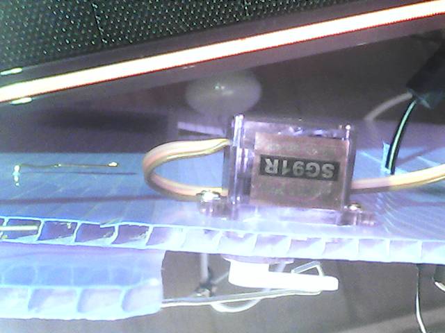
- hardware integration SERVO as optional I/O
with the servo there is the Volt / power question not same like with DALLAS sensors.
the DALLAS sensor can work from 3 to 5VDC, but when it gets 5V and it talks to DUE it might burn the D4 input.
so i connected it to 3V3 only and it worked.
for the SERVO i need 4.8 to 6 VDC as supply, it not talks to arduino,
but it gets the pulse signal, and from DUE it will be < 3V3. lets see if he accepts it.
but first use the MEGA hardware to get it running >=-1 for a special purpose what is called "HELD IN LOOP"
means the output is not send to hardware, but it can be read by a down / slave loop as CASCADE setpoint to make a loop loop connection.
and for this actual job SERVO i will use:
PID[x].OUTchannel=-2 and then D9 as SERVO puls output ( while PID[x].OUTchannel=9 could be normal PWM )
but then SERVO can not be used by other loop!
So its time to restart my testfield: HEAT CONTROL VALVE and Temperature sensor
and connect to PID[0] "TRC01-01" of the uPCS.
NO, because there still the Leonardo is mounted, i first update the PID_google04 to PID_google05 ( with better DALLAS timing and DALLAS address, and repair some menu code..)
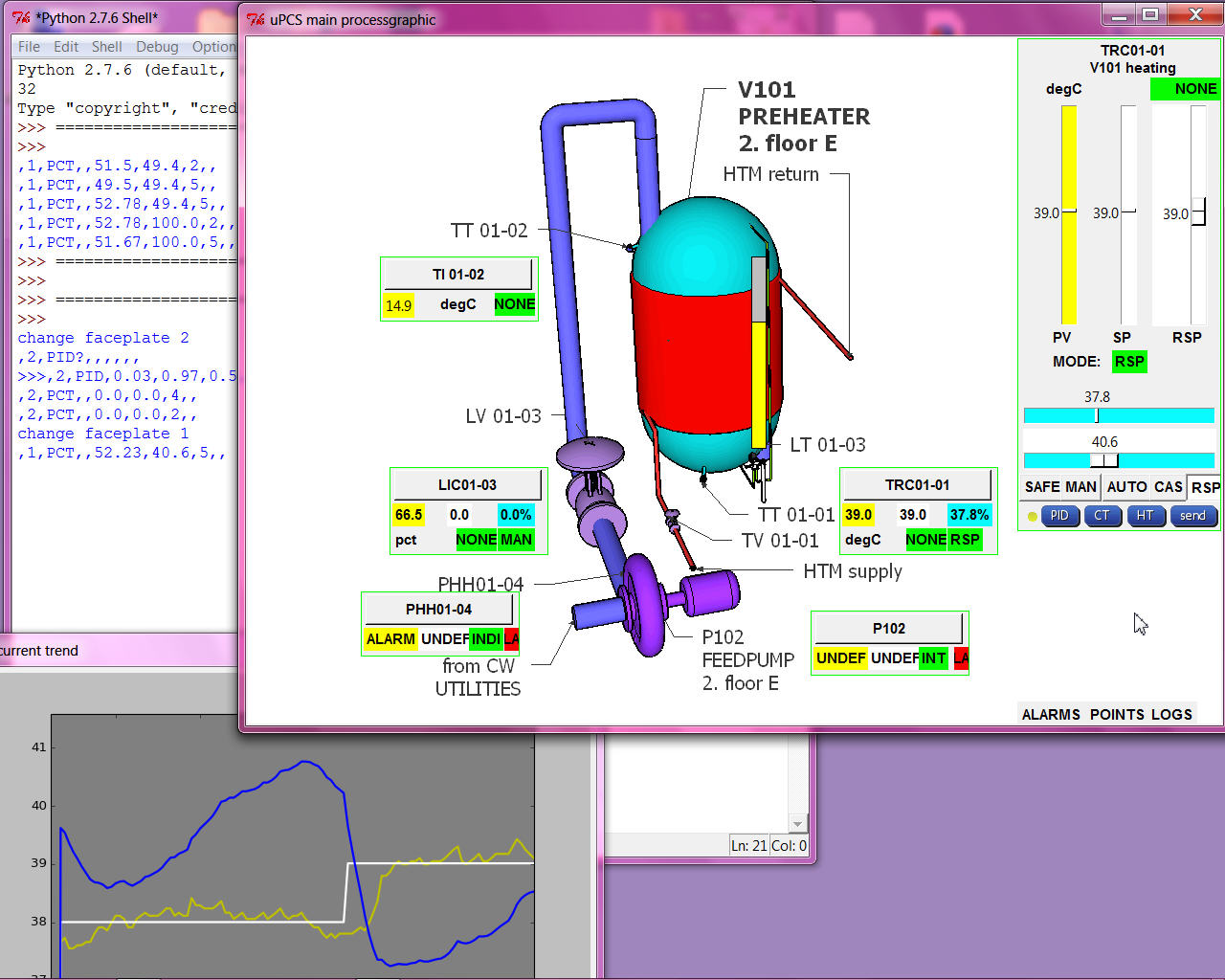
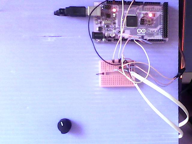
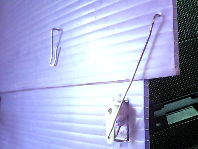
here first run of uPCS on MEGA with DALLAS sensor and SERVO plus operation on PC
left: using MEGA and USB to PC ( also as powersupply ) and setpoint poti for TRC01-01 and a breadboard as cable management. right: my heat valve ( triangle hole and rotating flap to close it ) background the lamp, front the DALLAS temperature sensor.
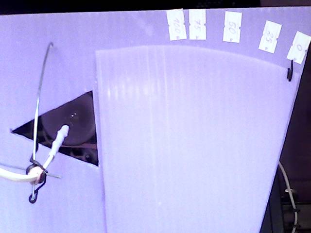
and its actuator with servo motor
now, as the test with the MEGA worked only the last step ( of porting the UNO PID project to DUE uPCS ) is missing:
test if the DUE can talk ( via D9 3v3 puls level ) with the servo ( what is powered by 5VDC ) (OK)
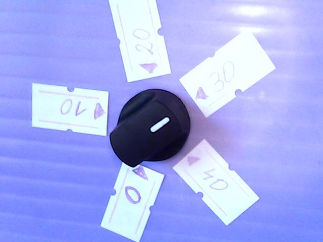
and install a nice setpoint (5k) poti too. The setpoint must be in the same range as the PV, means -55 to 125 degC, but the setpoint poti should have a calibrated ( software zoomed ) range ( hardware range MEGA(0 .. 5 ) DUE(0 .. 3.3 ) VDC on A1 ) to understand as example: 0 .. 40 degC or it would be unusable.
in the point config:
PID[0].SPT = 0.0;
PID[0].SPchannel = 1; // A1 poti
PID[0].hwinlo = 0; // N of 1024 = 0.0%
PID[0].hwinhi = 1023; // M of 1024 = 100.0%
PID[0].SPT_mapl = 30.5550; // PCT as 0 degC // map poti in the range
PID[0].SPT_maph = 52.780; // PCT as 40 degC
in the PID calc use:
pid->SPT = map(analogRead(pid->SPchannel),pid->hwinlo,pid->hwinhi,int(pid->SPT_maph*100),int(pid->SPT_mapl*100))/100.0;
ok, i twisted low and high or i would have to change the red / black wire from poti, to have the correct rotation also.
- DCP loopcheck until now i did not test that DCP examples, now, as the current trend is ready for that too, i can start. actually i want build a "hardware partner" for the M21 DCP where i can monitor the DCP inputs and output,
also i could feed the 2 inputs with timing.. like a test program with a UNO 2 outputs ( and the uPCS DCP on MEGA ), but for tests with / against the DUE board i could not use it because of the 3V3 range. So best is to start with a 3 line analog logging, that works fine for both boards.
but lets start with the easy one:
-A-
DCP[1]: template A10, the PV: 0 == ALARM, 1 == normal
DCP[1].PVchannel1 = 12; // 1 hardware input for the PV
DCP[1].SPchannel1 = 0; // no local operation
DCP[1].OUTchannel1 = 0; // no setpoint / outputs
and in interlocks() ( page PCScontrol bottom ) pls find:
// DCP[0] DCP1 interlock if DCP[1] DCP2 is ALARM
if (( DCP[1].alarm == 2 ) && ( DCP[0].intenable > 0 ) ) { DCP[0].mode = 1; } // write hard every cycle
here we have to check:
- if the digital input is high PV normal, low PV ALARM, means build in wire break detect (OK)
- interlock works (OK)
-- problem is the default DCP (mini)faceplate show setpoint and mode, what is not possible for that point.
here i change in arduinooperation2.py for the DCP mini faceplate and for the faceplate that the DCP loop template is checked and SP and MODE and MODE operation is shown accordingly.
-B-
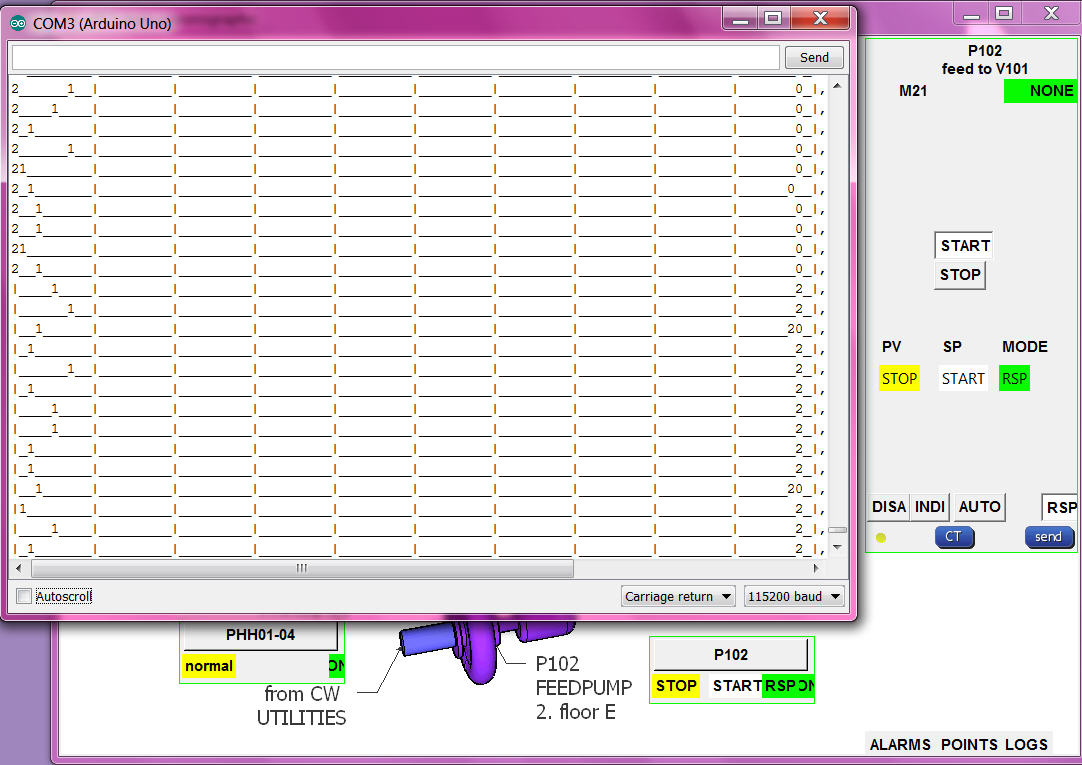
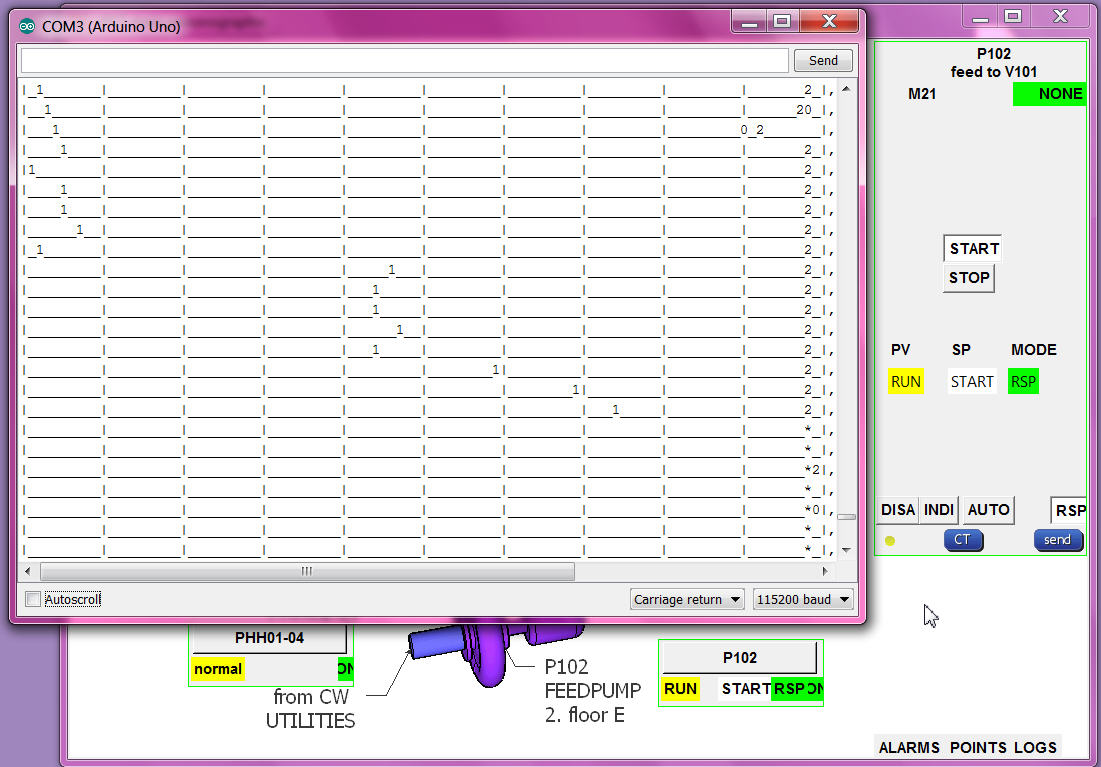
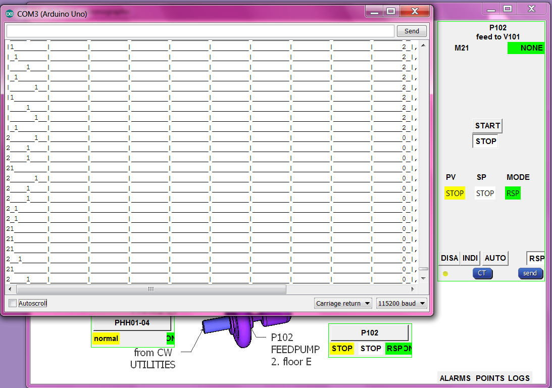
DCP[0]: template M21, the PV: 0 FAULT (00), 1 STOP (10), 2 RUN (11)
DCP[0].SPchannel1 = 13; // hardware input for setpoint ( LOCAL START/STOP latching )
DCP[0].PVchannel1 = 7; // hardware input for process value --> bit 0 (NOT FAULT)
DCP[0].PVchannel2 = 8; // hardware input for process value --> bit 1 ( RUN)
DCP[0].OUTchannel1 =10; // hardware output // 9 is now used for SERVO
at first there was a break in the chain of command:
the operation send
,8,PCT,,1,,5,, via the command file,
the stream read the command file, but DBI 8 was not encoded to send "R".
now DCP[0] SP and MODE write to arduino works, and send back in "PCT" info also.
possibly i should delete that "DBI check" at that place, the stream has to do what the operation wants???
anyhow the commands via "R" are to be checked by arduino again.
for the logging i use the PMS33 ( Poor Man Scope ), initial delaypoint = 12 ( non batch / conti mode 400ms )
//#define usePROCESSING == enable terminal mode line chart and size to fit in UNO.
and longer wires to jumper to the breadboard. there i can simulate the inputs 7,8 manually
and see in linechart: 7=> line0, 8=> line1, 10=>line2
in minifaceplate, faceplate, linechart:
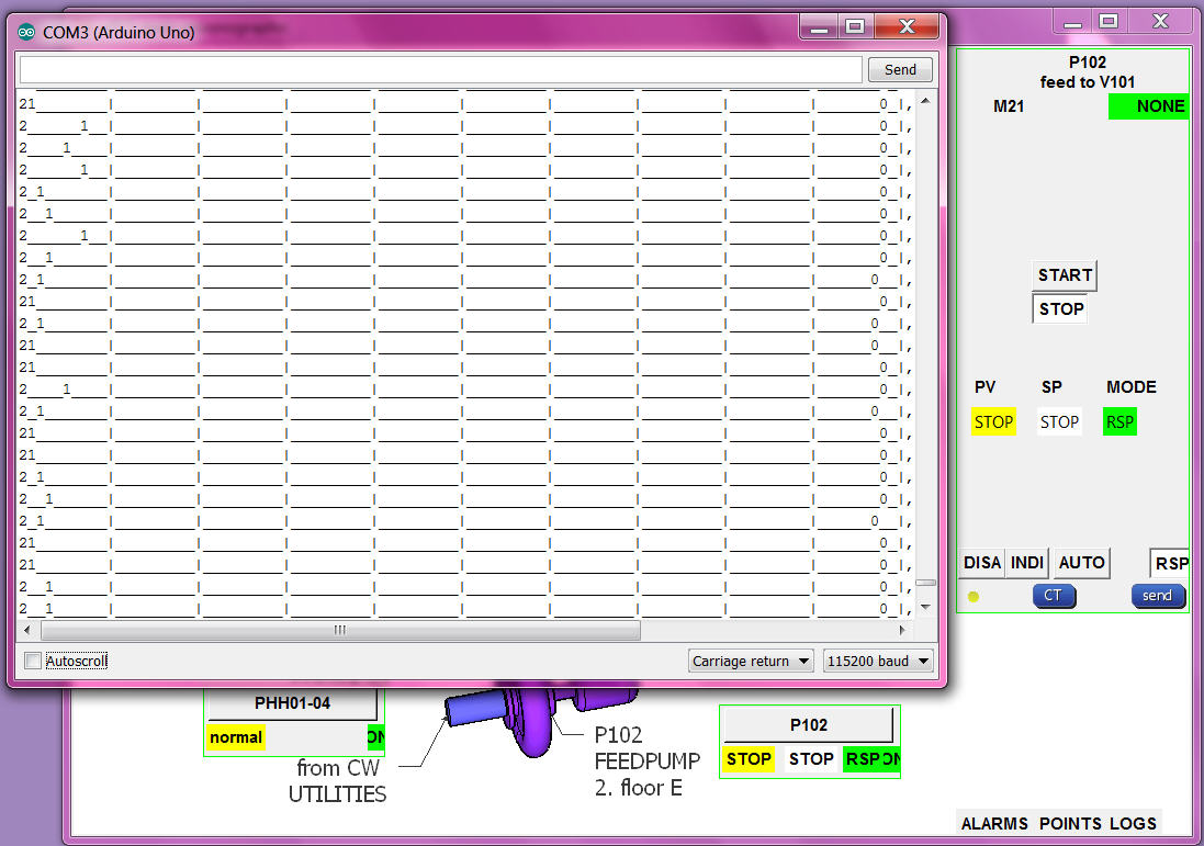
from the input pins ( their levels ) to the input combination, to the PV enumeration, transport to operation, translated to words (OK)
RSP setpoint button/word to RSP number send to arduino and drive output (OK)
but the alarming needs a more detailed check:
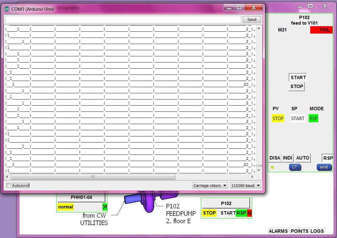
RSP:
if PV RUN and SETPOINT START alarm "NONE" and then the PV goes to STOP alarm go "FAIL" (OK)
if PV RUN and SETPOINT START alarm "NONE" and then motor fault goes OFF and run still ON, the PV goes to UNDEF alarm go "ALARM" (OK)
if PV STOP and SETPOINT change to START alarm "NONE" .. after delaytime "FAIL" (OK)
AUTO:
if MODE AUTO and SETPOINT STOP and then local setpoint input goes HIGH, SETPOINT goes START, OUTPUT HIGH, if PV not follow ALARM FAIL. (OK)
if MODE AUTO and SETPOINT START and then local setpoint input goes LOW, SETPOINT goes STOP, OUTPUT LOW, if PV not follow ALARM FAIL. (OK)
if MODE AUTO the RSP setpoint buttons in faceplate are confusing (NOT HAPPY)
but if i hide them with what setpoint go back RSP mode??
INTERLOCK:
if PV RUN and SETPOINT START alarm "NONE" and then the PHH goes to alarm, MODE go to INTerlock, OUTPUT goes OFF, (OK)
_ _ also can not change mode (OK)
_ _ but SP show UNDEF and no alarm (NOT OK) ! now show SP STOP, MODE INT, alarm ALAR, (OK)
_ _ when PHH ok can send RSP and SETPOINT again. (OK)
DISABLE:
SETPOINT START and change MODE to DISable (0) output still HIGH (NOT OK) ! now same as MODE INT, OUTPUT goes OFF, (OK)
- control hardware uPCS should run on chipKIT MAX32 also (OPEN)