
ARDUINO uPCS
65 ARDUINO uPCS
PROCESS MAIN GRAPHIC
as i know from some PCS Process Control Systems / DCS Distributed Control Systems and also from Visualization Systems / Operator Stations of PLC Progammable Logic Controller there are many different Graphic editors to engineer the Operator Station Graphics.
I will not try any of that here again in PYTHON, even i see there are power full graphic design tools for python available.
First i strictly separate static and dynamic part of that.
For the static i think best is a public free 3D tool like Sketch Up ... and just make a screen shot to a *.jpg
and use that as background and overlay dynamic indicators and links.
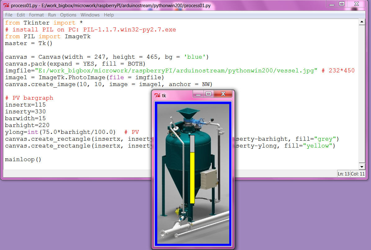
First i need to test if that is possible anyhow, so i borrow a picture and try a bargraph for level indication.
the slider i used in the PID faceplate are unusable here because of the width and the not transparent background, so i made it manually by 2 rectangles and its even better as the Tk slider.
now i am confident i should go that way, even making the required dynamic prototypes might take some time and also i am not very good with the sketch up 3D tool, i can ( and would ) not make a detailed static process graphic like i used above for the test. Actually i think that level of detail only distract the operators, more important is info like vessel name ( possibly location ) / loop name, all what they need to shout out to the field operators via the speaker system.
( But i know you can impress some boss with that show pictures at the sales demonstration! )
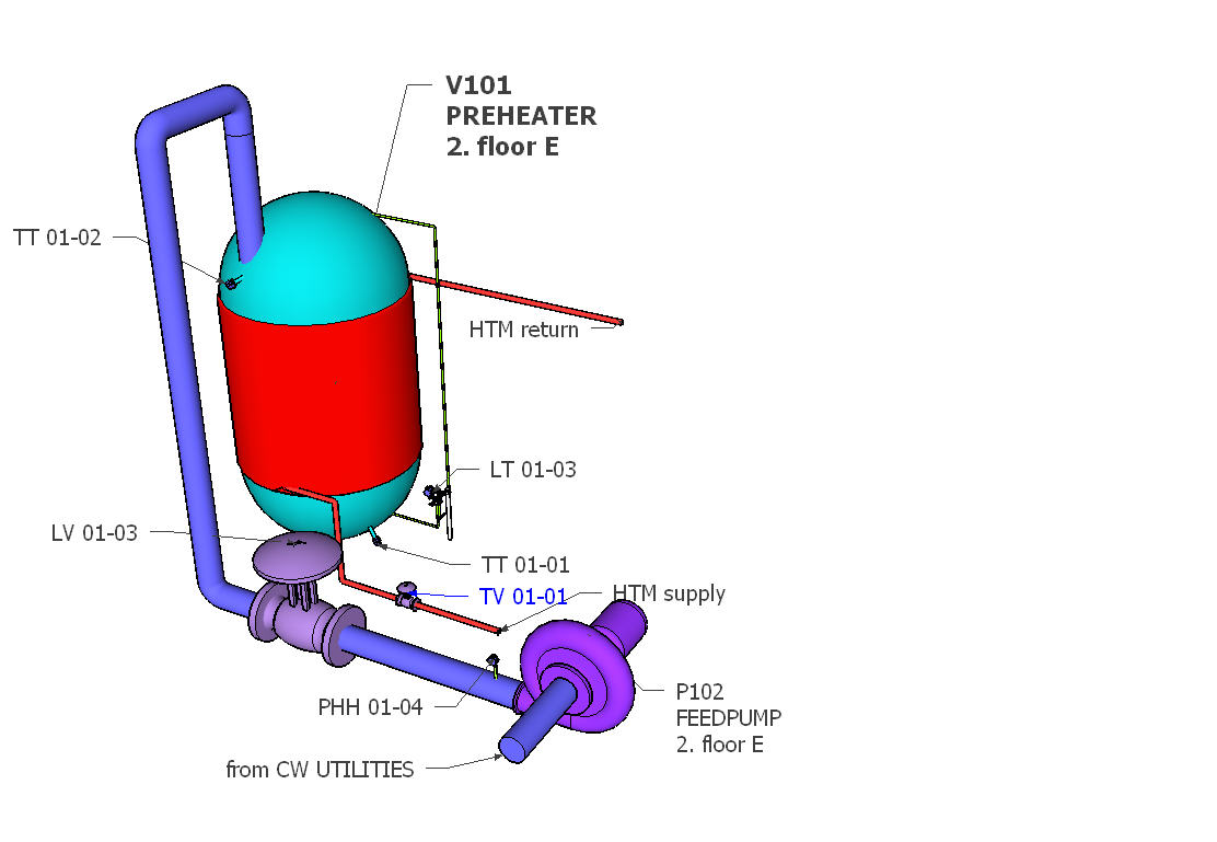
here my first ( SKETCH UP MAKE 2014 ) idea:
and using SKETCHFAB (exporter), pls use firefox, there move, rotate, zoom, fullscreen works!
operatorstation01
by kllsamui
on Sketchfab
i can not yet start with the dynamic, i know most of the work will be the positioning ( of the dynamic elements), means i need the window layout first fixed.
and problem / smallest window will be full screen from RPI in VNC window to PC ( and that's the way i need to use it ).
So try to set it up in RPI and i am not able to install PIL with IMAGETK for the background photo. I try 2 ways ( from forum) what not work and i don't know what i damaged.
Now i make my snaps as *.gif ( also the *.png files not readable ) and can start.
Here i want try a design with a "docked" faceplate window right side, while trend and tune can be pop up windows.
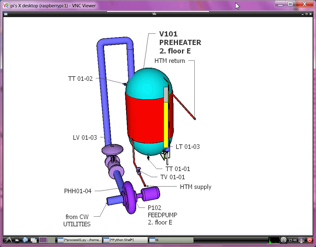
the VNC window is 1024 * 768, the max program window about 1020 * 718 ( decorated / with window head and border ). i need to cut my *.gif that way. ( using GIMP on PC as on RPI no tools installed)
in the VNC window that windowtest on RPI comes up like
OH, i not give up!
try again with
sudo apt-get install python-imaging
sudo apt-get install python-imaging-tk
and use
from Tkinter import *
from PIL import ImageTk
canvas = Canvas(width = 1020, height = 718, bg = 'blue')
canvas.pack(expand = YES, fill = BOTH)
#imgfile="/home/pi/arduinoproject/vesselV101.gif"
imgfile="/home/pi/arduinoproject/snap-014.jpg"
#image1 = PhotoImage(file = imgfile)
image1 = ImageTk.PhotoImage(file = imgfile)
canvas.create_image(0, 0, image = image1, anchor = NW)
and now also see a JPG! ( shading is much better ??)
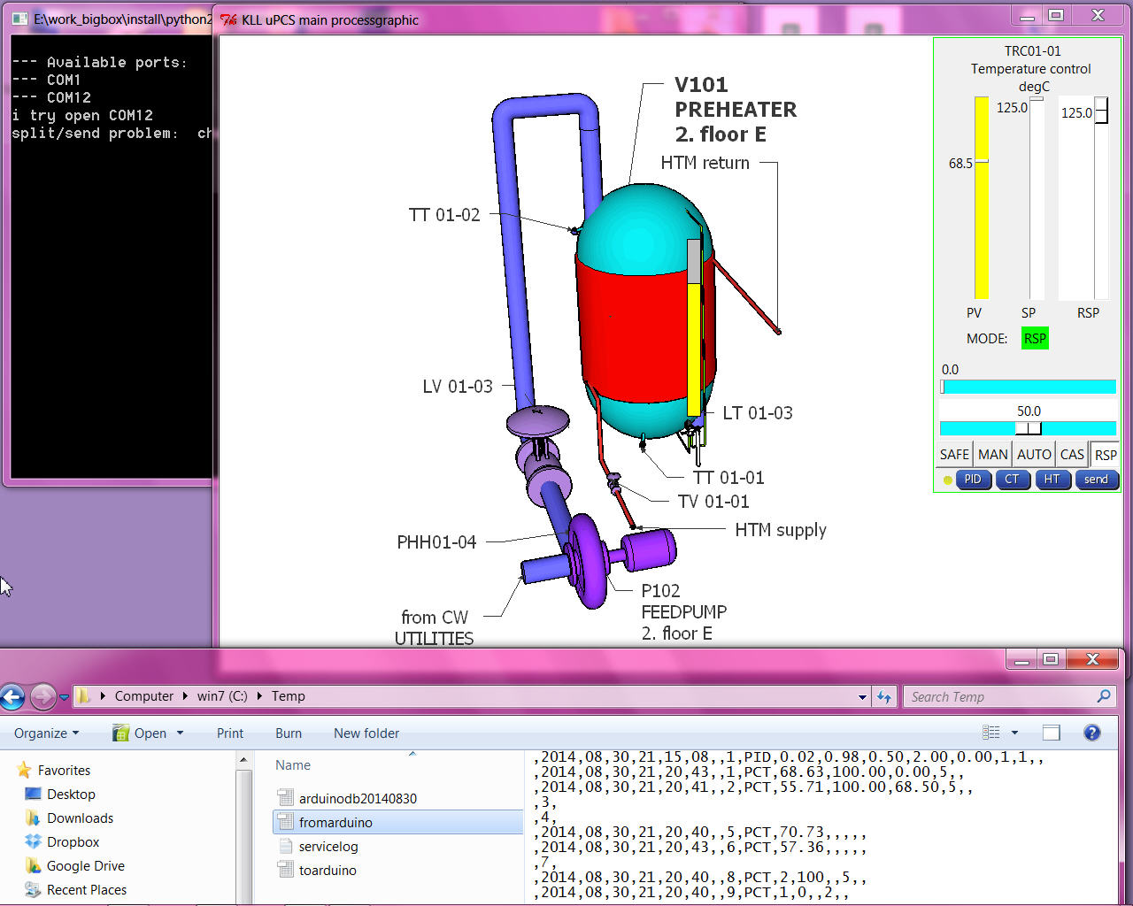
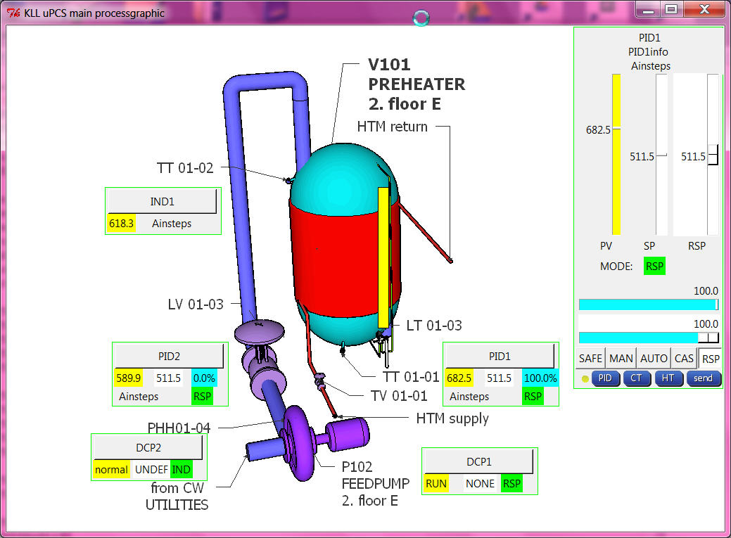
for the docked faceplate use one more canvas rectangle background on top of the picture,
and then draw the PID faceplate nearly again, by deleting frames and pack
and make pixel placement instead, also change the MODE buttons.
It still only "knows" one point but just to show the new layout
But to deal with multiple points it is not enough that we have the 10line "fromarduino.csv"
A operator station has to know much more, there is a point database required with
loop name("TRC01-01"), loop description("preheater temp"), EGU ( "degC"), EGU low("-55"), EGU high("125"), ...
what has to be linked with the arduino data LINE via DBI. also need point type to select different FACEPLATE types.
like for DCP where also template PV and SP WORDS are needed ( PV ==1 >> "STOP" ...)
so i could start type all that in lists in the operation python code OR
why not dynamic upload it from the arduino at operation startup?
( back documentation from arduino i already prepared in manual menu mode see here from page 5 on )
ok, that's a bigger change:
send by stream to arduino a call menu "P" ( compiler switch )
and then stream has to wait for 10 ( 9+1 ) line ( ignoring possible PCT info lines ) and save them to a new pointdb file.
and operation has to read the file and set point info in array, prior to show any dynamic values in faceplates...
as i go back arduino IDE with DUE, i will also improve diagnostic PID detail calc ( as i used in UNO already to find out why the output not move ( menu [d] toggles the piddiag )
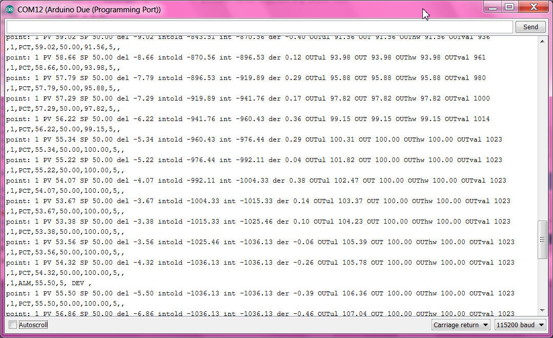
here you can follow how
- the integral part grow and increase the output,
- at 100.0% the output limit gets active,
- over 105 % the ARWUH "anti reset wind up high limit" freezes the integral part ( so if process recovers PID would be faster back in control range )
First i think to add optional I/O dallas temperature sensor and servo output,
but because of the DUE 3V3 I/O it might be tricky / i have to find out later /
for the MEGA it is useful anyhow.
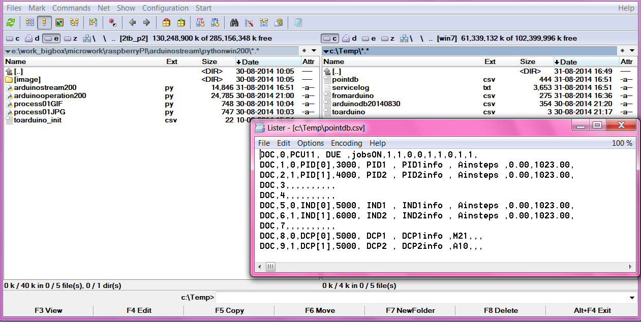
that is the basic loop info, the lines could grow longer but as we do the export read only at startup
there can not be any variable info in it, like PV,SP,mode or tuning variables.
now with that 2 files i should build up a big array with structure like [ name ( string), PV ( float), mode (int) ]
i even know in arduino how to do, but not in PYTHON. after a short read i give up and make simple lists,
all 10 long, with index = DBI ( 0 unused ):
strings: pTAG ( all names ) , pDESC ( all descriptions), pEGU ( all engineering units ),
real: pEGUL ( low range ), pEGUH ( high range )...
what makes it easy readable
and if there is a new point in arduino ( download from IDE )
at restart of stream and operation ( python tools in PC or RPI )
no coding is required, all data are available for that new DBI.
( you would need to change the static picture and make a dynamic+link there for the new point )
here the change from the default point config in arduino to this example process
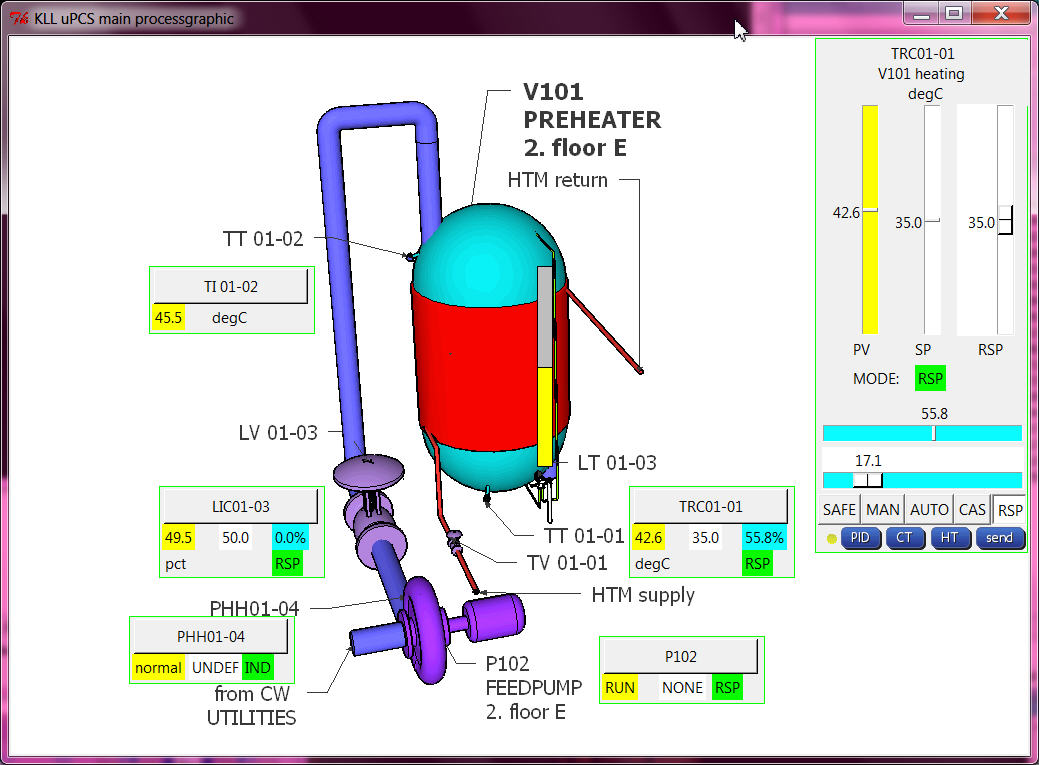
after service is stopped, arduino IDE, change 1min, download to DUE/MEGA, restart service
and all tag, desc, egu and range info is there! As perfect it looks, it is contrary to the work with a big PCS, there that info is not even required in the controller, it can be updated with a "partial download" to the operator stations. process would not have to be disturbed!
Here i did the bad thing: " TOTAL DOWNLOAD"
one of the difficult things is the faceplate select function( in the mini faceplate in the process graphic the loop name is a button, on click the faceplate should look at that loop point.
i need to do a faceplate in the main window ( docked, not a window), and when i need it for a new DBI it must be deleted and drawn again with new content, regarding point type and DBI info. So here the test about that xxx.destroy() of a frame. All the __self__ and class things i tested but did not really help.
actually the problem was to handle the frame from inside functions it must be declared globally. ( i use python 2.7.6 win 7 PC), pls try: frameexample
And just to mention one of my basic operation principles:
in a process graphic you can click where you want, max what will happen is that you select a loop point ( to faceplate )
in the faceplate you can click on slider for RSP / MOUT, MODE button,
or function button HT ( historic trend), CT (current trend), PID ( loop tuning),
still nothing is happening. you talk to the real world by pressing the [SEND] button only.
It might be nice to close cascades or start motors from a button in the graphic, but its also dangerous.
I can not recommend that. This you can design / program if you are the only operator later.
with all 3 point types and 3 faceplates ( and mini faceplates for process graphic )
the python operation program transfer from the UNO one PID control to DUE PID, IND, DCP already looks good. but still have to work on:
- PID tuning ( PID 1,2 ok ?i needed a delay timer?)
- hist trend
in google only 3 columns prepared for PID1 (ok)
- current trend
OLD: PID1 every sample PV/SP/OUTPUT max 900 samples
NEW:
2 PID PV/SP/OUTPUT/MODE (ok) ( mode * 10.0 to show better in range)
2 IND PV (ok)
2 DCP PV/SP/ MODE (ok)
without use more memory about 200 samples should be possible ( i worry RPI so start with 100 / tune later on RPI)
- alarming
first there should be a dedicated alarm log file ( ok: alarmlogfile is "alarmdb.csv" )
and that should be callable from process graphic.
( ok: 3 new buttons in main process display: ALARMS, POINTS, LOGS,
as 2 are .csv and one .txt i read them and write them to a temporary "showhtmlfile.html"
and with "file:///" and with ramdisk path and that filename i call the webbrowser to show them. )
( now it works in RPI and PC )
and the alarm should be shown in (mini) faceplate! what means it must be in the
fromarduino.csv ( or new file?) --> new pALM[DBI] also. ( ok )