
ARDUINO uPCS
65 ARDUINO uPCS
now my first tests with the PID control:
MAN output 100% / 255, DAC 2.75V to red LED and 220ohm show a PV of 19% at the resistor.
That would be 0.66V or 2.9mA. recheck with DMM, change 220ohm to 110ohm but only get 4mA.
and as the resistor smaller, the PV go even down further to 16.6%,
but i could zoom it by hwinhi from1023 to 200.
On the low range the current starts to flow at output 55%, 1.75V,
that i now connected to IND1 ( A5 ), no need to measure any more with DMM. The LED is ON in following range:
PID1 OUT 55%, PV=0%, IND1 PV= 53% ( 0mA )
PID1 OUT 100%, PV=16.7%, IND1 PV= 77% (4mA)
now in AUTO i see that the SP ( in above PV range ) can be reached,
but example SP 13%, output jumps 232 to 233, the PV 12.9 to 13.09, need to increase the output resolution, try first 10Bit.
now with DAC 930 ( of 1023 ) PV and SP 13.0.
i think there is also a correlation between that output resolution and the epsilon ( integral enable low limit ).
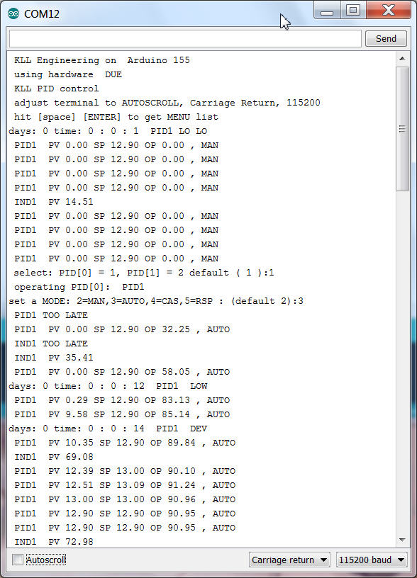
You see boot and switch PID1 to AUTO and reach SP.
operation: [M][enter](for MODE)[enter](for default PID1)[3][enter](for AUTO)
i think it should work on MEGA too,
( possibly find some other way for analog output ) ( for UNO its too big already )
i check it. now the DAC0 and DAC1 get compiler switches and are remapped to PWM 5 and 6
and the compiler got into a real big problem with my variable "pid[].SP" for setpoint.
some conflict with board type MEGA. i need to rename it to "SPT".
the analog output resolution also need compiler switches, DUE 1024 resolution 10bit , AVR 255.
i worry that somewhere in the code i got sloppy with the INT and LONG while i used DUE.
the INT 32000 limit with AVR can produce bad errors.
from now on it is not a DUE limited project, but still a DUE test.
and i have to learn it the hard way!
starting with the digital point type i write too complicated code without first testing the I/O.
and bad luck, nothing worked. diagnostic print into detail showed me that no digitalread worked
with DUE.
after i set the mode to input ( on AVR usually not need ) the reading worked, the not connected pins
are HIGH. ( on AVR LOW ) ?PULL UP? default?
now have the first step.
the configured ( up to 5 input channels ) inputs are set ( if HIGH ) as bits in a integer PVbin
what can be 0 ..31.
channels with a config like pin 0 ( <2 ) will not be set as input and not read,
and stay 0 at the corresponding PVbin bit. actually you could ( bad style ) disable channels this way
without changing the rest of the config. But better use example: 3 bits => channel 1 ,2 3. with PIN 3,4,5.
Now this PVbin is the inputcombination, not the PV
here example M2x a MCC with 2 wires to input, wire 1 for NOT FAULT and wire 2 for RUN.
PV0 is X, word is "undef"
PV1 you set to 1 ( 01 ), word is "STOP"
PV2 you set to 3 ( 11 ), word is "RUN"
a 0 is fault, we show undef OR configure it as a PV, but not needed.
a 2 is a error, RUN but FAULT should not happen, we also not configure, will show undef.
all PV0 undef will give a ALARM. and for a M20, a motor MCC indicator thats it.
for a M21, with SP START there will be a alarm on SP <> PV after timeout.
there is a mode operation for that template AUTO and RSP
where the setpoint comes from hardware input(s): a field switch ( latching)
or from menu USB.
Now here you have to expect the usual conflicts:
if mode is RSP but field operator want switch off motor??? ( i read but not use the hardware SP! in RSP )..
or is that local operation already solved in the MCC, what we have to do? follow our RSP setpoint
to the local SP / the PV? but possible with latching outputs a field start is anyway not possible...
a other point i prepared is a A10 a simple alarm point.
no SP, no MODE, the alarm wording is a question:
if PV0 "UNDEF" and PV1 "ok" i can write the PV text, or the word "ALARM"
but if i need to write "HIHI" for one loop and "LOLO" for an other i would need to distinguish
them by different templates... so better give that loop, a flow switch A10 template ( one input ) a good name like "FA4711LOLO", FALL4711 correct but not so good, and i will show you "ALARM" or "ok" depending on the input.
further parts:
a interlock program is called from the mail loop ( too often )
and set the mode of a PID loop or a DCP loop to INTerlock on a condition:
like:
void interlocks() {
// here we do the interlocks outside of any loop and read write in global names.
// PID[0] PID1 interlock if IND[0] IND1 is HIHI
if (( IND[0].alarm == 4 ) && ( PID[0].intenable > 0 ) ) { PID[0].mode = 1; } // write hard every cycle
// DCP[0] DCP1 interlock if DCP[1] DCP2 is ALARM
if (( DCP[1].alarm == 2 ) && ( DCP[0].intenable > 0 ) ) { DCP[0].mode = 1; } // write hard every cycle
} // end interlocks
while the mode is overwritten again and again i prepared a tuning possibility to disable the interlocks to one loop there. if that is disabled, the mode is still in INT, but now can change the mode. ( i know, that interlock disable tuning should be password protected! )
and a new menu entry "P" like document Print..
first get a list of all loops, can select one
and get a detailed list of all parameter, config incl. actual values PV, SP, mode, alarm
in a "parameter,value," list.
this is not only for documentation or your tuning update in code,
its the first step to enable a visualization system ( like processing )
to get all values about a loop.
[P][enter]
[1,2,5,6,8,9][enter]
not a efficient communication, but avoids double configuration of control and visualization system.
after getting all configuration of a point, the communication could be reduced to changes only.
now what above list not contains are the "words" for mode, alarm, DCP PVs and SPs.
but that are essential for the visualization system!
now i could send the words like i do it in the USB log, but that would not help for
a selection of example: setpoints for a Motor on the operator interface, where you need the full list of options first.so i also created a list of all that words just by printing them all.
[P][enter]
[0][enter]
because i want take a break here
little bit documentation of this 1.0.0 beta status
it contains
2 PID control with alarm
2 Ain with alarm
2 DCP (M21) and (A10)
I/O
PID1: PV A0
PID1:SP A1
PID1:OUT DAC0 ( no DUE PWM D5 )
PID2: PV A2
PID2: SP A3
PID2: OUT DAC1 ( no DUE PWM D6 )
IND1: PV A5
IND2: PV A6
(high / 1 means:)
DCP1: IN1 D7 "NO FAULT"
DCP1: IN2 D8 "RUN"
DCP1: OUT1 D9 "START"
DCP1: SP: D12 "START"
DCP2: IN1 D10 "NO ALARM"
operation from field:
PID1 SP ( if mode AUTO )
PID2 SP ( if mode AUTO )
DCP1 SP ( if mode AUTO ) switch closed START switch open STOP
operation from USB
PID1 MODE MAN OUTPUT MOUT (0..100%)
PID1 MODE AUTO
PID1 MODE CAS ( not connected )
PID1 MODE RSP RSP (0..100%)
PID2 MODE MAN OUTPUT MOUT (0..100%)
PID2 MODE AUTO
PID2 MODE CAS ( not connected )
PID2 MODE RSP RSP (0..100%)
DCP1 MODE MAN ( indicator only)
DCP1 MODE AUTO
DCP1 MODE RSP RSP 2 "START" RSP 1 "STOP"
interlocks
IND1 HIHI : PID1 mode INT
DCP2 ALARM : DCP1 mode INT
USB menue and operation (LOG) here
pls download