ARDUINO uPCS
Posted by kll on January 27 2014 19:33:25
uPCS ? i started with testing a PID control on a arduino DUE ( because that has 2 analog outputs and is faster ), but also runs on arduino MEGA ( using PWM or SERVO as analog outputs),
and i made a export of one PID control and run it on UNO/Leonardo/microPRO/
but the project grow so fast, i made it a new article about software modules you would need for a
micro Process Control System.
1. this list
2. add PID control points
3. add INDicator points
4. add Digital Control Points
5. menu operation, back documentation, download
6. step 2 multipoint data file, python service
7. main process graphic static, dynamic ( mini faceplates ), faceplate for operation
8. RPI install routine
9. more work
10. parts list
ARDUINO DUE ( part 2 )
- a - signal generator ( pls see here )
- b - PID control
there are some arduino PID code projects out there, but i want do my own version:
- its an old hobby, i did my first 1984 for a Z80 slave controller ( CPM / Pascal / ASM )
- + and that was already with proportional auto tuning ( adaptive gain) !
- i design control structures and program DCS ( distributed or process control systems ) for 20 years
- i made a arduino PID version already for my uDuino DIY LINK SLAVE, but because i stopped
with that link software i never used / tested the PID code.
design ideas ( will be updated while i work ):
- hardware I/O
- - PV (A0) ( sensor )
- - SP (A1) ( poti )
- - OUTput (DAC0) ( to actuator )
- USB menu program
( pls note, as the DUE not has EEPROM that menu tuning adjustments are only temporary,
for a stand alone controller RSP setpoint, initial mode, PID tuning must be updated in the code )
- - input of RSP ( remote set point )
- - input of OUTPUT ( set output ( setpoint of MAN MODE ))
- - input of MODE ( MAN, AUTO, RSP, CAS )
- - input of TUNING
- - - PV input filter (t)
- - - output invert ( y / n )
- - - output lo, hi limit
- - - PID action ( reverse / direct )
- - - P ( gain )
- - - I ( reset )(t)
- - - D ( rate )(t)
- - - cycle time t
- - input of ALARM tuning
- - - PV lolo, lo, hi, hihi
- - - deviation ( PV - SP )
actually filter reset and rate are time depending values, so for the setup of a PID controller
the cycle time must be fixed, or, if that is tunable too, that 3 values must depend on it.
as the PID algorithm will be run by 1 conti job,
even more pid controller / or other jobs could be activated,
then a recheck of controller load is required / depending on that tuned cycle time.
( minimum a error msg ( via US on TOO LATE for cycle time )
so, that's the outer frame for the PID control function
lets start with the USB menu program we used above for that fast speed / benchmark test.
general operation via the USB menu:
menu 1:
the default is PID1 is enabled.
with 1 you stop the conti job PID1, and again with 1 you start it and can provide a cycle time
( initial default is 1000msec / by enter like bad / no number / [space]... or wait 30sec input timeout )
or better, default is last input.
so remember when you later in the tuning get 20 questions to provide settings, each question can be skipped by [ENTER] also [space] ( or any other BAD input )
DAC output:
now i read in forum that lots of users burned the DAC ( mostly with connecting a speaker ).
I think it should be able to drive 15mA to a load, what would be in my case a diode ( LED) and a resistor , what i think is a easy and perfect PROCESS to control.
The OUTPUT == DAC Volt,
the PROCESS VALUE == the volt on the resistor ( to A0 ) and that corresponds with the current in the diode.
the resistor would be ( 3.3V - 1V diode )/ 0.015A <= 153ohm, usually 220
but actually DAC output range is 1/6 x 3.3V = 0.55V to 5/6 x 3.3V = 2.75V,
and the voltage on a LED diode varies not only with current, also with color...
software: instead of just copy and paste my old control software and fix it until running,
i got the idea it must be special, i wanted to prepare all for multiple PID loops running.
- make a struct definition of a data set of a PID controller
- make a array with 2 ( N) of this sets for 2 PID controller
OR make 2 named sets
- find a way to call a function ( THE PID function ) what can not only use also operate that data, so they are also available in the main loop.
later when i needed a tuning function and a operating function, i used the same trick,
first ask what controller you want to tune / operate, then call a function pointing to it.
and i must admit that is a little above my head and arduino documentation is not too helpful here.
lucky i found that mentioned in the forum, in between many not working other C code.
it is one way to do it, try to take a close look on the pointer in the function call and the handling of the pointed values in there.
i reduced it to a 2 variable example just to show how it can work. while for a array there is a easier way, ( just pass the index to the function and use normal handling global data there ) in example 2 where i used 2 named sets, you understand that the pointer thing is the only way.
 $('#zoom_24').elevateZoom();
  $('#zoom_25').elevateZoom();
here the first look at the menu and the ( temporary) tuning
already 2 PID controller build in, default only PID1 started.
 $('#zoom_26').elevateZoom();
  $('#zoom_27').elevateZoom();
  $('#zoom_28').elevateZoom();
- c - Indicator points
and also 2 analog indicators build in, with PV lolo lo hi hihi alarm, what later can be used for PID controller interlocking.
as usual in PLC programmable logic controller and DCS distributed control systems the controller only works with analog values in 0.0 .. 100.0 ( %), one decimal with the 10bit resolution.
while on the visualization level also need to configure x to Y low and high range and a engineering unit (like 200 .. 2000 L/min )
i will implement that into the processing ( operation ) part of that project later,
in the USB terminal LOG that is optional ( see tuning ), if enabled it works on the PV indication, and
also for SP indication and RSP setpoint input! but without changing the control code/values.
Also on the hardware level some adaption is needed, industrial thinking of analog values is 4 .. 20mA. ( at 24VDC supply) by 2 or 3 wire type sensors, normally closed the loop by a 250ohm measuring resistor ( or even 2 for a second safety limit monitoring circuitry ) what is giving 1 .. 5 V to differential input of a AD.
But even i work with it 20 years i do not know about a IC.. to handle that part in a sensor.
its just to tell you that here with our 0 .. 3.3V AD inputs and our 0.55 .. 2.75V DAC outputs
we might need electronic what could cost more as our analog I/O cpu "DUE" to be compatible
to industrial standard. But definitely we must understand about that LIVE ZERO / broken wire detection / thinking.
here how the PV input now look like:
input mapped hwinlo / hwinhi to 0.0 / 100.0 ( and numeric filtered )
( it may not be limited! in case of a LIVE ZERO signal we get a -PV on broken wire,
and a PV LOLO alarm can bring the PID control to a safe interlock mode... )
pid->PV = pid->PV * pid->PVfil0 + map(analogRead(pid->PVchannel),pid->hwinlo,pid->hwinhi,0,10000)/100.0 * pid->PVfil1;
// expect 3.3V >AD> 1023 = hwinhi, to make 100.0 recursive digital filtered PID PV
for the IDE,
27.1.2014 i download the nightly build ( 1.5.6 beta ) and upload my program,
and when i started the terminal it shows the first line ( send from arduino DUE)
and stopped with error.
Exception in thread "EventThread COM12" java.lang.NullPointerException
at processing.app.Serial.serialEvent(Serial.java:176)
at jssc.SerialPort$EventThread.run(SerialPort.java:1096)
back to 1.5.5. r2 ?fix? ok
- d - digital type points
as we now have PID control points and analog indicator/alarm points we need
something more: Digital Control Points.
that DCP is just a word, what means:
1 .. N digital inputs can be used to form bit patterns what can be assigned to show a PV
( 01 STOP, 11 RUN, 00 FAULT )
using only one input you can assign 2 words, a ON word and a OFF word.
and optionally can configure one if them to be the ALARM word,
( like: 1 "ok", 0 "( temperature oven ): HIHI" alarm )
( here see again, good thinking, wire break gives alarm )
( so DCP also covers a digital in indicator and a digital in alarm type )
add you can assign 1 .. M digital outputs ( latching ) and bit patterns with SP words.
SP0 1 (START)
SP1 0 (STOP)
in case one digital output and no digital input its a usual Dout, ( with 2 assigned SP words )
but with inputs ( feedback ) following feature is possible.
operator action: select a SETPOINT
DCP drives the corresponding bit combination to the assigned outputs.
after a configured timeout the input combination (PV) is checked and if not match
a alarm is generated.
SP START, after 6 sec. PV != RUN >> FAIL ALARM.
also if after successful "start" later the PV changes like PV RUN to PV FAULT
also a FAIL ALARM is created.
And at last even a SP sequence can be generated ( each with timer )
operator select SP START
-1- DCP drive SP 01 RESET
-2- if PV after timer is not 01 STOP ( like 00 FAULT ) alarm
if ok in time: drive SP 10 START
-3- if PV after timer is not 11 RUN alarm
OR
on SP START drive 10, after timer drive 00
to create pulses from latching outputs.
i know you all know, there are digital input and digital outputs
and they can be low or high. But i hope above thinking
of DCP is useful to deal with it in a more structured way.
you think that i talk old fashioned electric? a Motor Control Center with 3 inputs and 2 outputs "M32" wired to a I/O card?
yes and no, because if today the motor, inverter.. is connected by fieldbus...
you have a SP (output) word and a PV (input) word by link, and the operation
software is still same, mapped to selected bits of these words.
and a pneumatic diverter valve with 2 proximity sensors for the position ( Valve 2 inputs, 2 outputs "V22" ) still might need digital wiring old style.
but for the digital I/O same as with the analog I/O, a output of 3.3Volt, can drive 15mA,
and a input 3.3V, damaged by 5V already?,
(with schmitt trigger 0.15V) see low at below 0.3*3.3V and high above 0.7*3.3V??
need to check that with DAC later,
its all far from industrial / electrical standards and need to be beefed up for power electric.
now my first tests with the PID control:
MAN output 100% / 255, DAC 2.75V to red LED and 220ohm show a PV of 19% at the resistor.
That would be 0.66V or 2.9mA. recheck with DMM, change 220ohm to 110ohm but only get 4mA.
and as the resistor smaller, the PV go even down further to 16.6%,
but i could zoom it by hwinhi from1023 to 200.
On the low range the current starts to flow at output 55%, 1.75V,
that i now connected to IND1 ( A5 ), no need to measure any more with DMM. The LED is ON in following range:
PID1 OUT 55%, PV=0%, IND1 PV= 53% ( 0mA )
PID1 OUT 100%, PV=16.7%, IND1 PV= 77% (4mA)
now in AUTO i see that the SP ( in above PV range ) can be reached,
but example SP 13%, output jumps 232 to 233, the PV 12.9 to 13.09, need to increase the output resolution, try first 10Bit.
now with DAC 930 ( of 1023 ) PV and SP 13.0.
i think there is also a correlation between that output resolution and the epsilon ( integral enable low limit ).
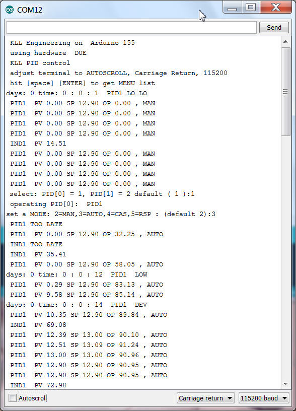
You see boot and switch PID1 to AUTO and reach SP.
operation: [M][enter](for MODE)[enter](for default PID1)[3][enter](for AUTO)
i think it should work on MEGA too,
( possibly find some other way for analog output ) ( for UNO its too big already )
i check it. now the DAC0 and DAC1 get compiler switches and are remapped to PWM 5 and 6
and the compiler got into a real big problem with my variable "pid[].SP" for setpoint.
some conflict with board type MEGA. i need to rename it to "SPT".
the analog output resolution also need compiler switches, DUE 1024 resolution 10bit , AVR 255.
i worry that somewhere in the code i got sloppy with the INT and LONG while i used DUE.
the INT 32000 limit with AVR can produce bad errors.
from now on it is not a DUE limited project, but still a DUE test.
and i have to learn it the hard way!
starting with the digital point type i write too complicated code without first testing the I/O.
and bad luck, nothing worked. diagnostic print into detail showed me that no digitalread worked
with DUE.
after i set the mode to input ( on AVR usually not need ) the reading worked, the not connected pins
are HIGH. ( on AVR LOW ) ?PULL UP? default?
now have the first step.
the configured ( up to 5 input channels ) inputs are set ( if HIGH ) as bits in a integer PVbin
what can be 0 ..31.
channels with a config like pin 0 ( <2 ) will not be set as input and not read,
and stay 0 at the corresponding PVbin bit. actually you could ( bad style ) disable channels this way
without changing the rest of the config. But better use example: 3 bits => channel 1 ,2 3. with PIN 3,4,5.
Now this PVbin is the inputcombination, not the PV
here example M2x a MCC with 2 wires to input, wire 1 for NOT FAULT and wire 2 for RUN.
PV0 is X, word is "undef"
PV1 you set to 1 ( 01 ), word is "STOP"
PV2 you set to 3 ( 11 ), word is "RUN"
a 0 is fault, we show undef OR configure it as a PV, but not needed.
a 2 is a error, RUN but FAULT should not happen, we also not configure, will show undef.
all PV0 undef will give a ALARM. and for a M20, a motor MCC indicator thats it.
for a M21, with SP START there will be a alarm on SP <> PV after timeout.
there is a mode operation for that template AUTO and RSP
where the setpoint comes from hardware input(s): a field switch ( latching)
or from menu USB.
Now here you have to expect the usual conflicts:
if mode is RSP but field operator want switch off motor??? ( i read but not use the hardware SP! in RSP )..
or is that local operation already solved in the MCC, what we have to do? follow our RSP setpoint
to the local SP / the PV? but possible with latching outputs a field start is anyway not possible...
a other point i prepared is a A10 a simple alarm point.
no SP, no MODE, the alarm wording is a question:
if PV0 "UNDEF" and PV1 "ok" i can write the PV text, or the word "ALARM"
but if i need to write "HIHI" for one loop and "LOLO" for an other i would need to distinguish
them by different templates... so better give that loop, a flow switch A10 template ( one input ) a good name like "FA4711LOLO", FALL4711 correct but not so good, and i will show you "ALARM" or "ok" depending on the input.
further parts:
a interlock program is called from the mail loop ( too often )
and set the mode of a PID loop or a DCP loop to INTerlock on a condition:
like:
void interlocks() {
// here we do the interlocks outside of any loop and read write in global names.
// PID[0] PID1 interlock if IND[0] IND1 is HIHI
if (( IND[0].alarm == 4 ) && ( PID[0].intenable > 0 ) ) { PID[0].mode = 1; } // write hard every cycle
// DCP[0] DCP1 interlock if DCP[1] DCP2 is ALARM
if (( DCP[1].alarm == 2 ) && ( DCP[0].intenable > 0 ) ) { DCP[0].mode = 1; } // write hard every cycle
} // end interlocks
while the mode is overwritten again and again i prepared a tuning possibility to disable the interlocks to one loop there. if that is disabled, the mode is still in INT, but now can change the mode. ( i know, that interlock disable tuning should be password protected! )
and a new menu entry "P" like document Print..
first get a list of all loops, can select one
and get a detailed list of all parameter, config incl. actual values PV, SP, mode, alarm
in a "parameter,value," list.
this is not only for documentation or your tuning update in code,
its the first step to enable a visualization system ( like processing )
to get all values about a loop.
[P][enter]
[1,2,5,6,8,9][enter]
not a efficient communication, but avoids double configuration of control and visualization system.
after getting all configuration of a point, the communication could be reduced to changes only.
now what above list not contains are the "words" for mode, alarm, DCP PVs and SPs.
but that are essential for the visualization system!
now i could send the words like i do it in the USB log, but that would not help for
a selection of example: setpoints for a Motor on the operator interface, where you need the full list of options first.so i also created a list of all that words just by printing them all.
[P][enter]
[0][enter]
because i want take a break here
little bit documentation of this 1.0.0 beta status
it contains
2 PID control with alarm
2 Ain with alarm
2 DCP (M21) and (A10)
I/O
PID1: PV A0
PID1:SP A1
PID1:OUT DAC0 ( no DUE PWM D5 )
PID2: PV A2
PID2: SP A3
PID2: OUT DAC1 ( no DUE PWM D6 )
IND1: PV A5
IND2: PV A6
(high / 1 means
DCP1: IN1 D7 "NO FAULT"
DCP1: IN2 D8 "RUN"
DCP1: OUT1 D9 "START"
DCP1: SP: D12 "START"
DCP2: IN1 D10 "NO ALARM"
operation from field:
PID1 SP ( if mode AUTO )
PID2 SP ( if mode AUTO )
DCP1 SP ( if mode AUTO ) switch closed START switch open STOP
operation from USB
PID1 MODE MAN OUTPUT MOUT (0..100%)
PID1 MODE AUTO
PID1 MODE CAS ( not connected )
PID1 MODE RSP RSP (0..100%)
PID2 MODE MAN OUTPUT MOUT (0..100%)
PID2 MODE AUTO
PID2 MODE CAS ( not connected )
PID2 MODE RSP RSP (0..100%)
DCP1 MODE MAN ( indicator only)
DCP1 MODE AUTO
DCP1 MODE RSP RSP 2 "START" RSP 1 "STOP"
interlocks
IND1 HIHI : PID1 mode INT
DCP2 ALARM : DCP1 mode INT
USB menue and operation (LOG) here
pls download
actually the work did not stop here, i just took a sidestep and exported one PID control with minimum functionality to run it in a UNO/Leonardo/ProMicro.
And connect it by USB to a Raspberry PI ( optional also a win7 PC ) and
feed data to a google spreadsheet as "historic datacollection"
As next step i make a operation program ( by python ) what adds faceplate, current trend and tuning for the PID control here
now we are back:
until now the operation of the uPCS was limited to the terminal window on the USB link to the arduino ( DUE / MEGA ) via the menu, now i want use the RPI with the mentioned python programs.
First i need to change in uPCS the arduino code similar, with the compiler switch for the operation menu manual / RPI.
and introduce the short CSV line reporting and tuning.
but there are always problems, in uPCS we have different loop points with different point types
and we have a 'new' feature, the alarming, what not follows my actual datastream from PID control
so the first connection ( DUE <--> RPI ) is some coding away.
most of it is just formatting the output from DUE to RPI ( if compiler switch is unset )
but i found a logical error in the existing communication,
Operation: "R" ",1,PCT,,RSP,MODE,,"
Tuning: "T" ",1,PID,....."
get Tuning "t" this can not work, arduino has to know it has to send actual tuning of WHAT point it only works now in UNO because there is only one point.
next error is about the startup, as the Leonardo does not init when connect / open serial from python i did not notice until now work with DUE ( programming port ) that the initial setpoint write from the init file ( first action, even before any ser. read ) does not work. DUE needs a 1sec delay to be ready for "R".... but possibly only when you connect DUE to a running PC and start service manually. when RPI and DUE are powered up same time it could work even without???
next step, as we have DBI 1,2,5,6,8,9 in uPCS prepared ( of 1 .. 9 conti jobs ) with 1,2 PID loops, 5,6 IND loops and 8,9 DCP loops,
i can not expect to transport each single reported line ( with added timestring ) in a one line file to the operation and being read from there in time.
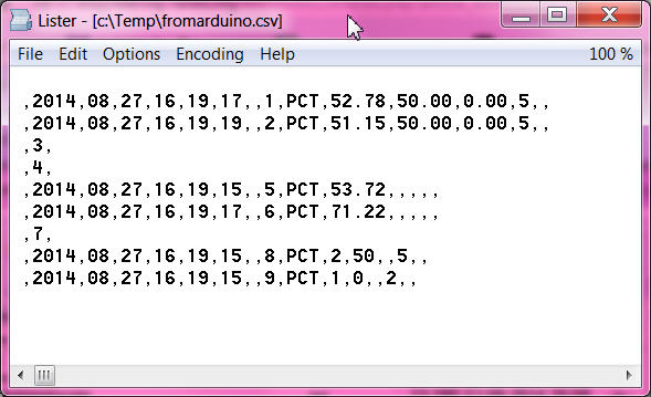
now i use a string array ( 0 .. 9 ) and store all PCT infos from arduino in line 1 .. 9 and optional PID reporting to line 0
and that i write to the FROMARDUINO.csv file every time a new PCT or PID line arrives.
Now the operation can read that now 10 line file and has all actual data with timestring ( each).
for the operation that has many consequences, it works and still starts with PID faceplate of loop DBI 1, what now not makes sense any more.
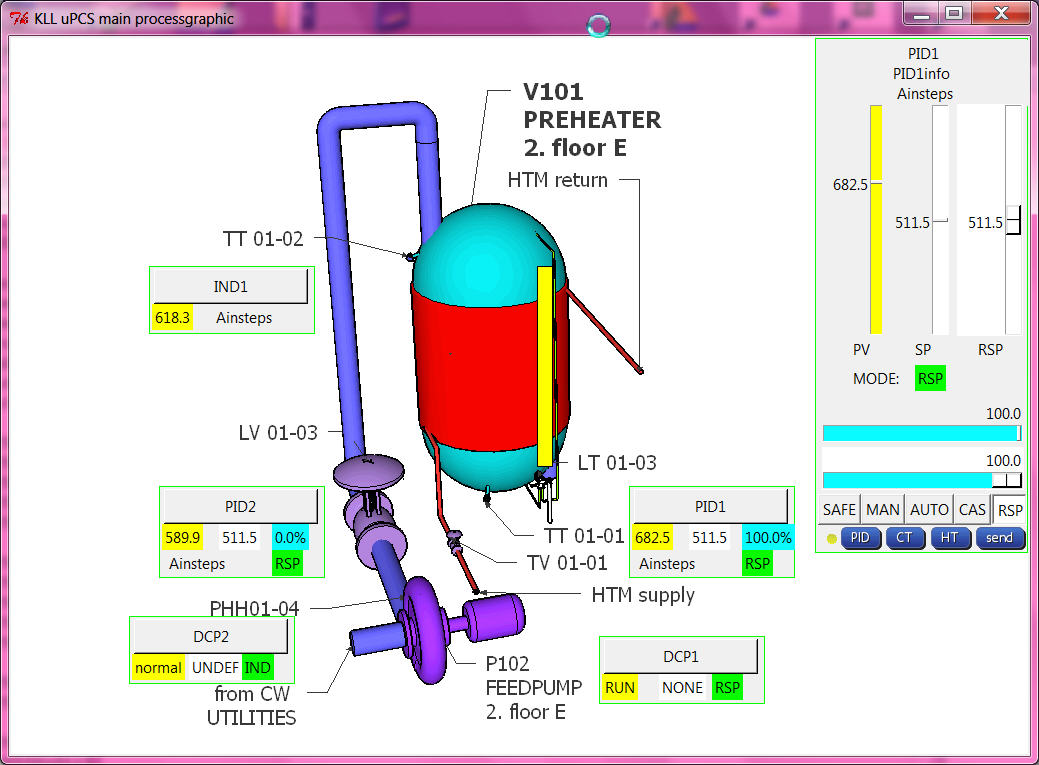
we need to start with a process picture now what contains dynamic elements of all loops ( mini faceplates ) with link to open the faceplate,
and there we need 3 type, PID prototype we have, IND and DCP point type must make new.
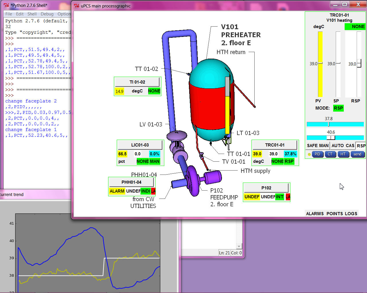
PROCESS MAIN GRAPHIC
as i know from some PCS Process Control Systems / DCS Distributed Control Systems and also from Visualization Systems / Operator Stations of PLC Progammable Logic Controller there are many different Graphic editors to engineer the Operator Station Graphics.
I will not try any of that here again in PYTHON, even i see there are power full graphic design tools for python available.
First i strictly separate static and dynamic part of that.
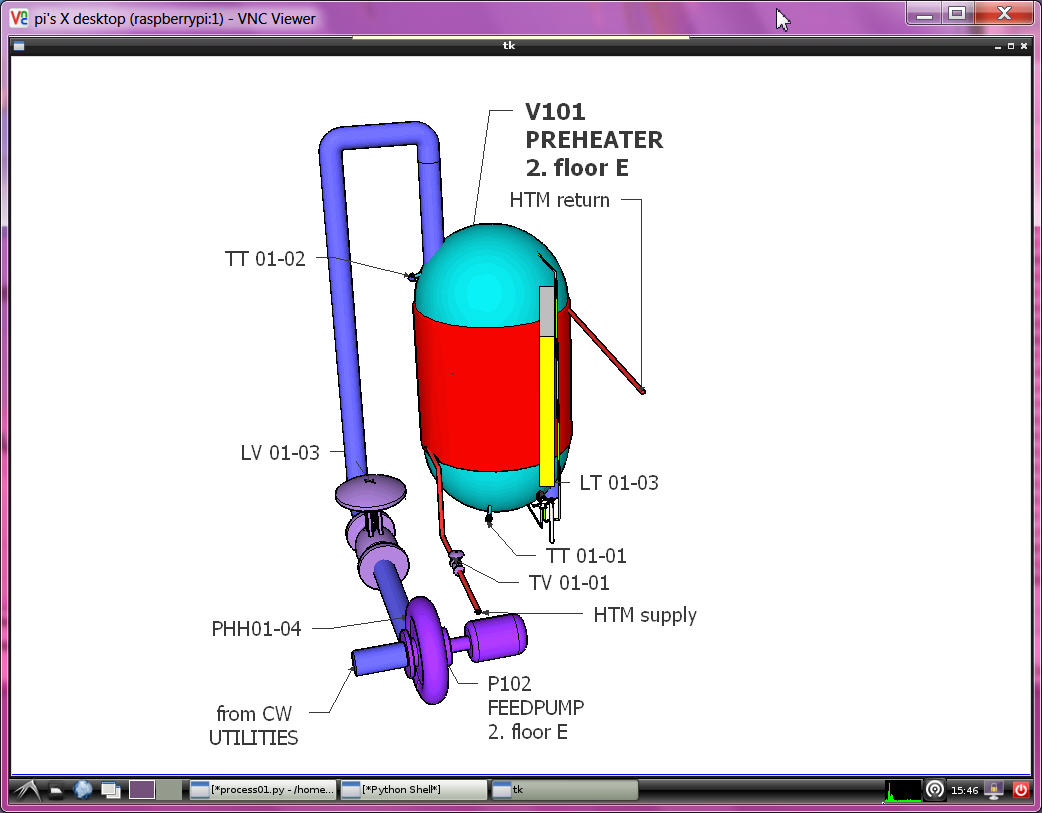
For the static i think best is a public free 3D tool like Sketch Up ... and just make a screen shot to a *.jpg
and use that as background and overlay dynamic indicators and links.
First i need to test if that is possible anyhow, so i borrow a picture and try a bargraph for level indication.
the slider i used in the PID faceplate are unusable here because of the width and the not transparent background, so i made it manually by 2 rectangles and its even better as the Tk slider.
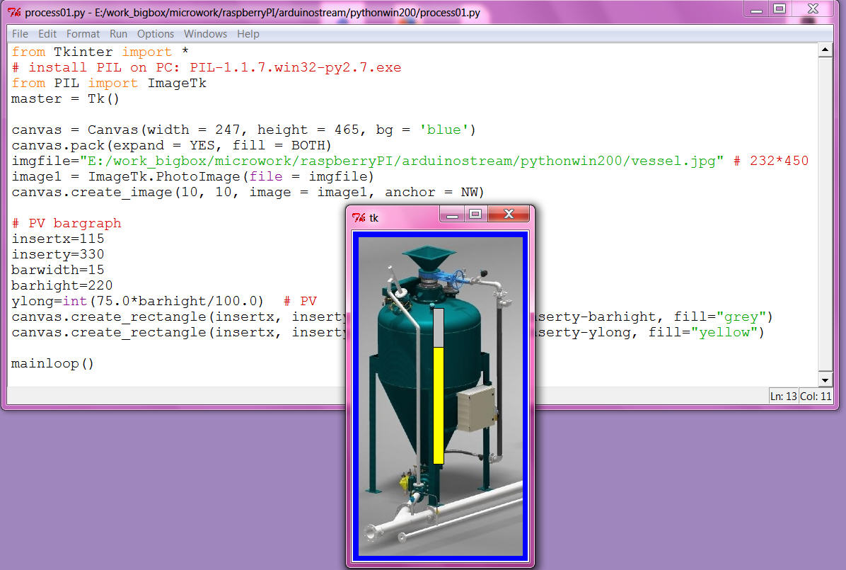
now i am confident i should go that way, even making the required dynamic prototypes might take some time and also i am not very good with the sketch up 3D tool, i can ( and would ) not make a detailed static process graphic like i used above for the test. Actually i think that level of detail only distract the operators, more important is info like vessel name ( possibly location ) / loop name, all what they need to shout out to the field operators via the speaker system.
( But i know you can impress some boss with that show pictures at the sales demonstration! )
here my first ( SKETCH UP MAKE 2014 ) idea:
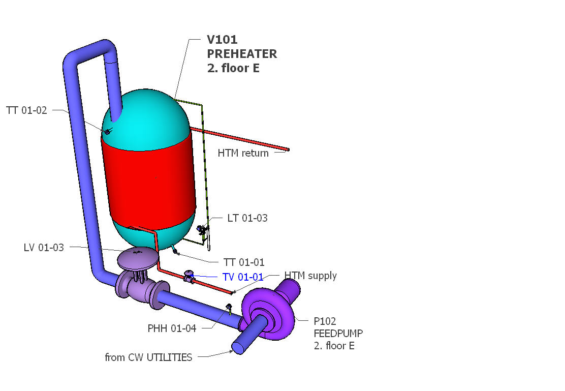
and using SKETCHFAB (exporter), pls use firefox, there move, rotate, zoom, fullscreen works!
operatorstation01
by kllsamui
on Sketchfab
i can not yet start with the dynamic, i know most of the work will be the positioning ( of the dynamic elements), means i need the window layout first fixed.
and problem / smallest window will be full screen from RPI in VNC window to PC ( and that's the way i need to use it ).
So try to set it up in RPI and i am not able to install PIL with IMAGETK for the background photo. I try 2 ways ( from forum) what not work and i don't know what i damaged.
Now i make my snaps as *.gif ( also the *.png files not readable ) and can start.
Here i want try a design with a "docked" faceplate window right side, while trend and tune can be pop up windows.
the VNC window is 1024 * 768, the max program window about 1020 * 718 ( decorated / with window head and border ). i need to cut my *.gif that way. ( using GIMP on PC as on RPI no tools installed)
in the VNC window that windowtest on RPI comes up like
OH, i not give up!
try again with
sudo apt-get install python-imaging
sudo apt-get install python-imaging-tk
and use
from Tkinter import *
from PIL import ImageTk
canvas = Canvas(width = 1020, height = 718, bg = 'blue')
canvas.pack(expand = YES, fill = BOTH)
#imgfile="/home/pi/arduinoproject/vesselV101.gif"
imgfile="/home/pi/arduinoproject/snap-014.jpg"
#image1 = PhotoImage(file = imgfile)
image1 = ImageTk.PhotoImage(file = imgfile)
canvas.create_image(0, 0, image = image1, anchor = NW)
and now also see a JPG! ( shading is much better ??)
for the docked faceplate use one more canvas rectangle background on top of the picture,
and then draw the PID faceplate nearly again, by deleting frames and pack
and make pixel placement instead, also change the MODE buttons.
It still only "knows" one point but just to show the new layout
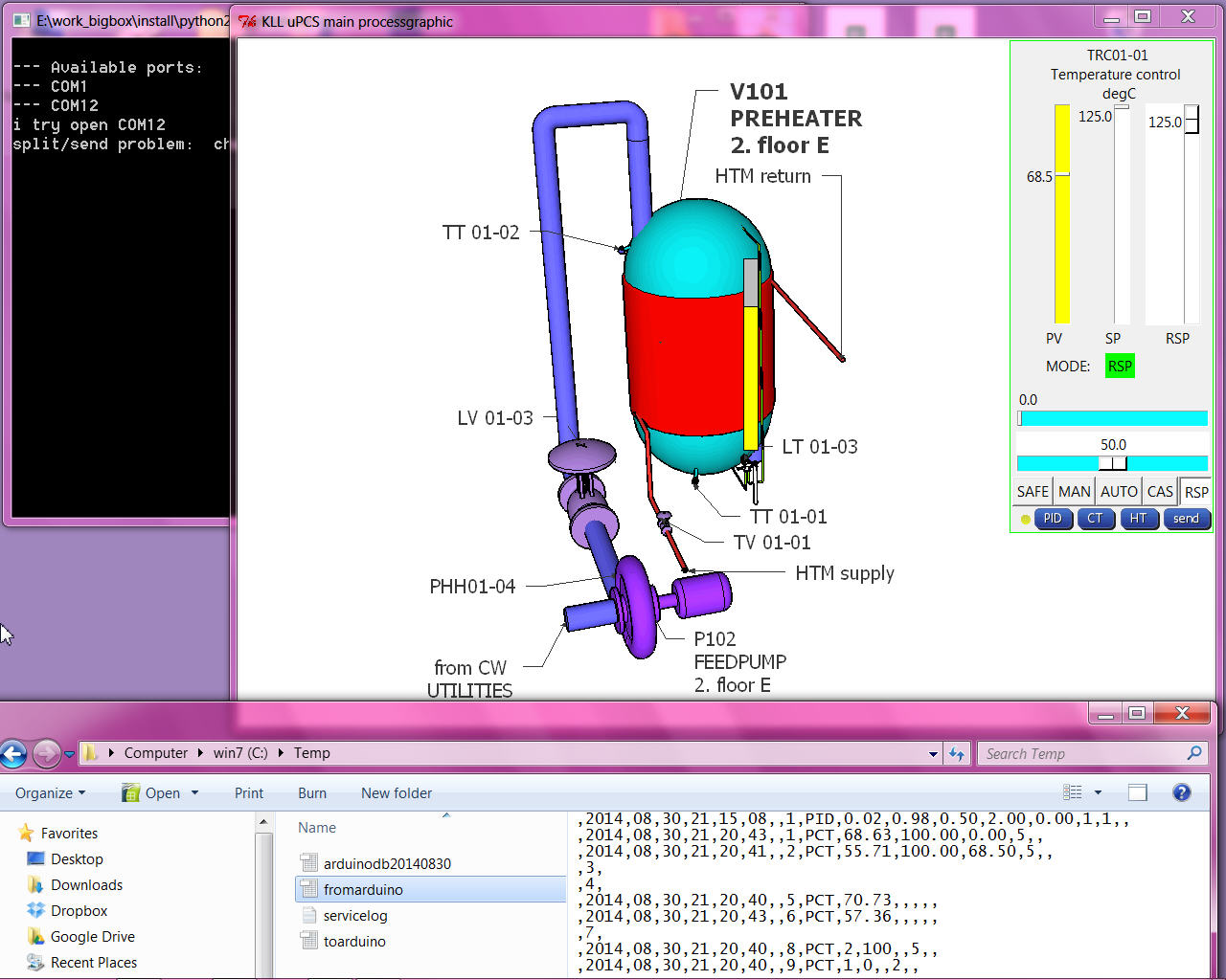
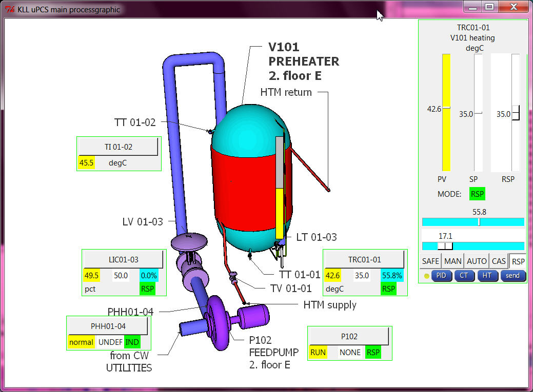
But to deal with multiple points it is not enough that we have the 10line "fromarduino.csv"
A operator station has to know much more, there is a point database required with
loop name("TRC01-01"), loop description("preheater temp"), EGU ( "degC"), EGU low("-55"), EGU high("125"), ...
what has to be linked with the arduino data LINE via DBI. also need point type to select different FACEPLATE types.
like for DCP where also template PV and SP WORDS are needed ( PV ==1 >> "STOP" ...)
so i could start type all that in lists in the operation python code OR
why not dynamic upload it from the arduino at operation startup?
( back documentation from arduino i already prepared in manual menu mode see here from page 5 on )
ok, that's a bigger change:
send by stream to arduino a call menu "P" ( compiler switch )
and then stream has to wait for 10 ( 9+1 ) line ( ignoring possible PCT info lines ) and save them to a new pointdb file.
and operation has to read the file and set point info in array, prior to show any dynamic values in faceplates...
as i go back arduino IDE with DUE, i will also improve diagnostic PID detail calc ( as i used in UNO already to find out why the output not move ( menu [d] toggles the piddiag )
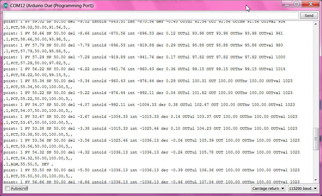
here you can follow how
- the integral part grow and increase the output,
- at 100.0% the output limit gets active,
- over 105 % the ARWUH "anti reset wind up high limit" freezes the integral part ( so if process recovers PID would be faster back in control range )
First i think to add optional I/O dallas temperature sensor and servo output,
but because of the DUE 3V3 I/O it might be tricky / i have to find out later /
for the MEGA it is useful anyhow.
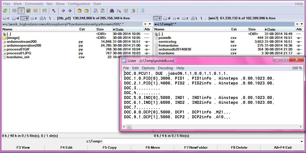
that is the basic loop info, the lines could grow longer but as we do the export read only at startup
there can not be any variable info in it, like PV,SP,mode or tuning variables.
now with that 2 files i should build up a big array with structure like [ name ( string), PV ( float), mode (int) ]
i even know in arduino how to do, but not in PYTHON. after a short read i give up and make simple lists,
all 10 long, with index = DBI ( 0 unused ):
strings: pTAG ( all names ) , pDESC ( all descriptions), pEGU ( all engineering units ),
real: pEGUL ( low range ), pEGUH ( high range )...
what makes it easy readable
and if there is a new point in arduino ( download from IDE )
at restart of stream and operation ( python tools in PC or RPI )
no coding is required, all data are available for that new DBI.
( you would need to change the static picture and make a dynamic+link there for the new point )
here the change from the default point config in arduino to this example process
after service is stopped, arduino IDE, change 1min, download to DUE/MEGA, restart service
and all tag, desc, egu and range info is there! As perfect it looks, it is contrary to the work with a big PCS, there that info is not even required in the controller, it can be updated with a "partial download" to the operator stations. process would not have to be disturbed!
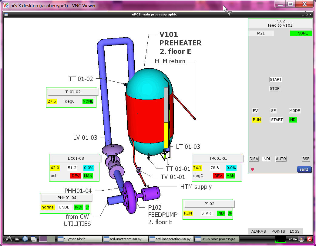
Here i did the bad thing: " TOTAL DOWNLOAD"
one of the difficult things is the faceplate select function( in the mini faceplate in the process graphic the loop name is a button, on click the faceplate should look at that loop point.
i need to do a faceplate in the main window ( docked, not a window), and when i need it for a new DBI it must be deleted and drawn again with new content, regarding point type and DBI info. So here the test about that xxx.destroy() of a frame. All the __self__ and class things i tested but did not really help.
actually the problem was to handle the frame from inside functions it must be declared globally. ( i use python 2.7.6 win 7 PC), pls try: frameexample
And just to mention one of my basic operation principles:
in a process graphic you can click where you want, max what will happen is that you select a loop point ( to faceplate )
in the faceplate you can click on slider for RSP / MOUT, MODE button,
or function button HT ( historic trend), CT (current trend), PID ( loop tuning),
still nothing is happening. you talk to the real world by pressing the [SEND] button only.
It might be nice to close cascades or start motors from a button in the graphic, but its also dangerous.
I can not recommend that. This you can design / program if you are the only operator later.
with all 3 point types and 3 faceplates ( and mini faceplates for process graphic )
the python operation program transfer from the UNO one PID control to DUE PID, IND, DCP already looks good. but still have to work on:
- PID tuning ( PID 1,2 ok ?i needed a delay timer?)
- hist trend
in google only 3 columns prepared for PID1 (ok)
- current trend
OLD: PID1 every sample PV/SP/OUTPUT max 900 samples
NEW:
2 PID PV/SP/OUTPUT/MODE (ok) ( mode * 10.0 to show better in range)
2 IND PV (ok)
2 DCP PV/SP/ MODE (ok)
without use more memory about 200 samples should be possible ( i worry RPI so start with 100 / tune later on RPI)
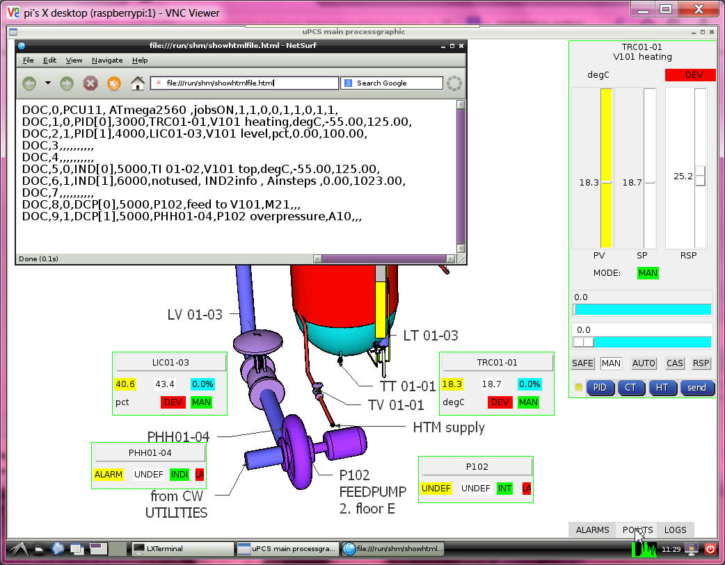
- alarming
first there should be a dedicated alarm log file ( ok: alarmlogfile is "alarmdb.csv" )
and that should be callable from process graphic.
( ok: 3 new buttons in main process display: ALARMS, POINTS, LOGS,
as 2 are .csv and one .txt i read them and write them to a temporary "showhtmlfile.html"
and with "file:///" and with ramdisk path and that filename i call the webbrowser to show them. )
( now it works in RPI and PC )
and the alarm should be shown in (mini) faceplate! what means it must be in the
fromarduino.csv ( or new file?) --> new pALM[DBI] also. ( ok )
i think here is a good status for a beta release V2.02:
UPDATE: now see here
again i did that from putty and got a 100% cpu load ( i see in VNC )
but after putty sudo reboot all ok
and the operation looks different from the win 7 PC, some default character size is different and changes the text and dynamics layout, and the faceplate background color also different. But pls find that now the alarming visualization in main process graphic and faceplate works.
means this was also for me the first test of the (big) uPCS on RPI, all coding i did on PC this time.
if the old version python service with UNO is installed, that service must be removed first
sudo update-rc.d -f arduinostream remove
you can not start 2 services on the same arduino USB link.
now a /power up / boot test i see again in ramdisk only the pointdb.csv, so need more start testing
of DUE on RPI, but service running, pointdb.csv means menu "P" to arduino and arduino send pointlist and
log to file ok. but no fromarduino.csv file ? very strange? a start from IDLE and all ok ? even more strange ?
at service restart all works but there is a OS message about program names should not be longer as 15 char??
so change 200 > 2 in all names.
now i think i need better glasses. i was looking in the pointdb file for the last line is 9 ok, but the line 0 is missing,
so it did not find 10 lines, only 9 and it got stuck in that loop.
there must be a serial problem about the first line after send "P" it not see line "DOC,0....." but only at boot/powerup even with a 2 sec delay to wait for DUE. ( delay in DUE to answer on "P" also no use , still loose first line )
ok, was a program error / tab indentation inside the "def get_pointdb()", this can happen with source transfer PC to RPI?
in the RPI forum i find a good info about how to work from PC on RPI:
- you can open 2 putty windows (ok)
- with notepad ++ can edit RPI files directly via SSH SFTP, a very good tool if you work headless, for python must adjust some things for "new files", and for edit:
/ settings / preferences / TAB settings / [python] or [replace by space] or you have indentation errors.
also with the PC IDLE problems, options configure IDLE tab, [ok], i must do everytime i use it?
looks like i have to cleanup my code first, best way still is to develop on RPI and copy the linux files back to PC.
use a downloaded DUE on RPI is no problem, but on arduino IDE on RPI ( rev 1.0.1 ) there is no arduino DUE,
so no download from RPI to DUE possible, i will test a download to a arduino MEGA now
-1- arduinostream2-service STOP
-2-1- arduino IDE select uPCS2
-2-2- arduino IDE select board "arduino MEGA 2560"
-2-3- arduino IDE check port
-2-4- arduino IDE upload ( first try timeout, second try ok )
-2-5- arduino IDE serial monitor ( see stream ) EXIT
-3- arduinostream2-service START
-4- check ramdisk files up to date
-5-1- start arduino2operation
-5-2- check new button [POINTS] in processgraphic ( and note the CPU info in first line: ATMAGE2560 )
still see a small wrong bordercolor about the sliders and smaller charactersize
in the new version i define a font with size, but still different in 2 PC and RPI
anyhow i prepare the automatic selection depending on OS.
much more to do!
- hardware integration DALLAS as optional I/O
i take the code and hardware DS18B20 with 3 wire and internal 4.7k "pullup" ( its a charge resistor )
from the UNO PID project, build in more diagnostic and find a double error in that code:
- the temperature shown was always 2 times the same value, because the code was in mode device search,
found one, show value, search for more, not find, but not reset that value, show same value again.
- and in the uPCS project first use MEGA hardware, i got LOOP TOO LATE after the DALLAS call. ( changed that time warning to 1sec )
now i changed the config, if PID PV channel / IND PV channel == -2
i expect a DALLAS device addr. like my DS18B20: 28 E2 83 3E 4 0 0 1F
if the DALLAS code is called and a device addr. is provided, it not search, it calls that device and is so a little bit faster.
but if i use the DS18B20 with 12 bit still need that wait 1 sec ( > 750ms )
in "boolean dallasdiag = false; " can select that detailed diagnostic. for your device need to find that addr. info first.
add i have a test in JOB4, pls set temporary "boolean exec4conti = true; " and find in terminal window
checkinbytearray 0 0 0 0 0 0 0 0 val 0
search
ROM = 28 E2 83 3E 4 0 0 1F
Chip = DS18B20
A9 1 4B 46 7F FF 7 10 85
type_s 0
cfg: 60
12 bit resolution
degC 26.56
,4,DEGC,26.56,,,,,,
.....
checkinbytearray 0 0 0 0 0 0 0 0 val 0
search
No more addresses.
,4,DEGC,-100.00,,,,,,
now use that ROM info to configure your PID[x].PVaddr[0..7] / IND[x].PVaddr[0..7]
( the uPCS ( on USB ) not show degC usually, only PCT )
and tests with DUE ( 4um )
now change over to DUE board and connect DALLAS "pullup" to V3.3,data(2) to D4, COM(1)(3) to GND,
hope, that sensor works with that volt, that lib works for DUE..
- compile upload ok, DALLAS sensor read ok, but even with 2000 get too late warnings??
i must find a other way as that delay(1000) inside the DALLAS CODE, arduino has better things to do as to sleep and wait for slow sensors. i have a good timer ( the JOB timer ) and what i need for DALLAS would be that 1sec prior to the loop time PV read, i start the sampling already.
other way would be to start the sampling directly after the last read and run the loop every second. fast but unclean
very tricky i do the dallas things now in the contijobs
and call read_DALLAS(int modesel=0) { // 0 do all( measure, wait, getdata), 1 do measure, 2 do get data
read_DALLAS(1) about 1 sec prior to the loop JOB
read_DALLAS(2) prior to the loop JOB
but now i see a other problem, if i have the configured device addr.
but the sensor is disconnected, i not see the reset -100degC.
this software just gives back a data array 0 --> 0degC
with using the "present" variable from reset, i can do a communications check, and only if true set the temperature value. // HOLD now on MEGA with NO DALLAS connected it again sees a 0 degC // actually there should be a switch in the library code to show the funny -85degC if no communication!
why -85? because on error sensor sends a 85degC ( what is bad because its a good value inside the range -55 .. 125 degC. )
and more problems, testing this with uPCS and MEGA with PID1 and IND1 use dallas sensor, and i mix DS18B20 and DS18S20 ( using only one with the resistor )
i get ( about every second time ) that 85degC, a indication that timing, power, network wiring not good. Funny is that if i enable JOB4, where the original dallas search code is used,
there it works, while at the same time for PID1 OR IND1 i see that 85, clear a sign that it is a timing/power related problem.
i need a new idea for multiple dallas parasite power wired, check here?
that complicated double timer for each point ( jobtime - 1sec -> start dallas ) (jobtime -> read dallas and do point)
with the different timing for the 2 points disrupts the dallas bus timing, possibly about charging..., i deleted it.
now i take the dallas network out of the points and give it a own JOB timed 1sec. as start i now need 4 steps / secs to read 2 sensors.
but it works. the ( 4 analog ) loop points now have their own dallas memory variable.
i will come back to this and test with one more sensor and try reduce timing again. but for now i want go on.
i have that basic cycle counter in my menu/multitasking program.
now with the 6 loop points enabled and timed: 2 PID 3sec, 2 IND, 2 DCP 5 sec i see 1.000.000 cycles in
8sec with DUE
27sec with MEGA
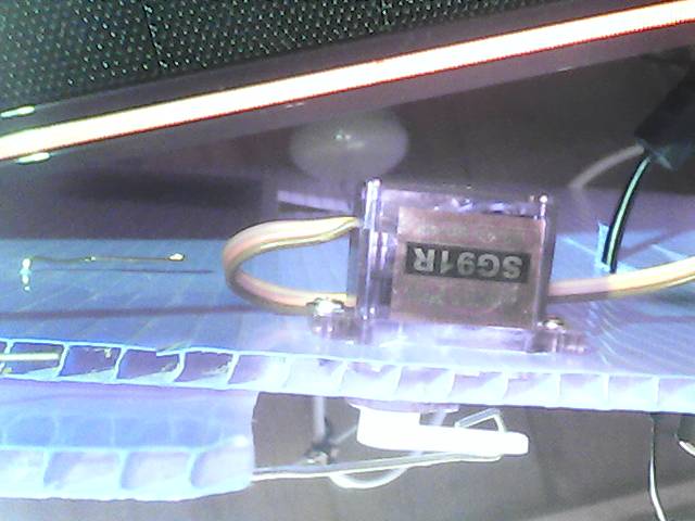
- hardware integration SERVO as optional I/O
with the servo there is the Volt / power question not same like with DALLAS sensors.
the DALLAS sensor can work from 3 to 5VDC, but when it gets 5V and it talks to DUE it might burn the D4 input.
so i connected it to 3V3 only and it worked.
for the SERVO i need 4.8 to 6 VDC as supply, it not talks to arduino,
but it gets the pulse signal, and from DUE it will be < 3V3. lets see if he accepts it.
but first use the MEGA hardware to get it running >=-1 for a special purpose what is called "HELD IN LOOP"
means the output is not send to hardware, but it can be read by a down / slave loop as CASCADE setpoint to make a loop loop connection.
and for this actual job SERVO i will use:
PID[x].OUTchannel=-2 and then D9 as SERVO puls output ( while PID[x].OUTchannel=9 could be normal PWM )
but then SERVO can not be used by other loop!
So its time to restart my testfield: HEAT CONTROL VALVE and Temperature sensor
and connect to PID[0] "TRC01-01" of the uPCS.
NO, because there still the Leonardo is mounted, i first update the PID_google04 to PID_google05 ( with better DALLAS timing and DALLAS address, and repair some menu code..)
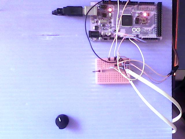
here first run of uPCS on MEGA with DALLAS sensor and SERVO plus operation on PC
left: using MEGA and USB to PC ( also as powersupply ) and setpoint poti for TRC01-01 and a breadboard as cable management. right: my heat valve ( triangle hole and rotating flap to close it ) background the lamp, front the DALLAS temperature sensor.
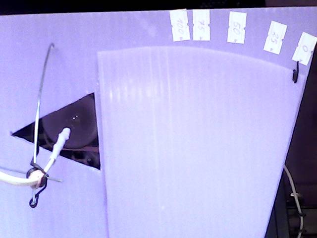
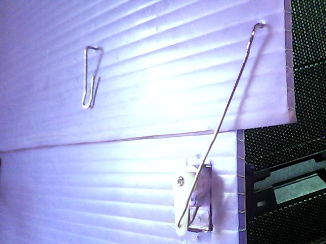
and its actuator with servo motor
now, as the test with the MEGA worked only the last step ( of porting the UNO PID project to DUE uPCS ) is missing:
test if the DUE can talk ( via D9 3v3 puls level ) with the servo ( what is powered by 5VDC ) (OK)
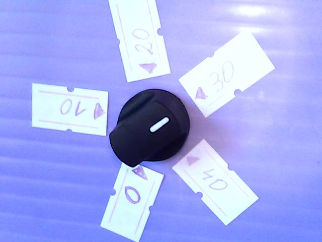
and install a nice setpoint (5k) poti too. The setpoint must be in the same range as the PV, means -55 to 125 degC, but the setpoint poti should have a calibrated ( software zoomed ) range ( hardware range MEGA(0 .. 5 ) DUE(0 .. 3.3 ) VDC on A1 ) to understand as example: 0 .. 40 degC or it would be unusable.
in the point config:
PID[0].SPT = 0.0;
PID[0].SPchannel = 1; // A1 poti
PID[0].hwinlo = 0; // N of 1024 = 0.0%
PID[0].hwinhi = 1023; // M of 1024 = 100.0%
PID[0].SPT_mapl = 30.5550; // PCT as 0 degC // map poti in the range
PID[0].SPT_maph = 52.780; // PCT as 40 degC
in the PID calc use:
pid->SPT = map(analogRead(pid->SPchannel),pid->hwinlo,pid->hwinhi,int(pid->SPT_maph*100),int(pid->SPT_mapl*100))/100.0;
ok, i twisted low and high or i would have to change the red / black wire from poti, to have the correct rotation also.
- DCP loopcheck until now i did not test that DCP examples, now, as the current trend is ready for that too, i can start. actually i want build a "hardware partner" for the M21 DCP where i can monitor the DCP inputs and output,
also i could feed the 2 inputs with timing.. like a test program with a UNO 2 outputs ( and the uPCS DCP on MEGA ), but for tests with / against the DUE board i could not use it because of the 3V3 range. So best is to start with a 3 line analog logging, that works fine for both boards.
but lets start with the easy one:
-A-
DCP[1]: template A10, the PV: 0 == ALARM, 1 == normal
DCP[1].PVchannel1 = 12; // 1 hardware input for the PV
DCP[1].SPchannel1 = 0; // no local operation
DCP[1].OUTchannel1 = 0; // no setpoint / outputs
and in interlocks() ( page PCScontrol bottom ) pls find:
// DCP[0] DCP1 interlock if DCP[1] DCP2 is ALARM
if (( DCP[1].alarm == 2 ) && ( DCP[0].intenable > 0 ) ) { DCP[0].mode = 1; } // write hard every cycle
here we have to check:
- if the digital input is high PV normal, low PV ALARM, means build in wire break detect (OK)
- interlock works (OK)
-- problem is the default DCP (mini)faceplate show setpoint and mode, what is not possible for that point.
here i change in arduinooperation2.py for the DCP mini faceplate and for the faceplate that the DCP loop template is checked and SP and MODE and MODE operation is shown accordingly.
-B-
DCP[0]: template M21, the PV: 0 FAULT (00), 1 STOP (10), 2 RUN (11)
DCP[0].SPchannel1 = 13; // hardware input for setpoint ( LOCAL START/STOP latching )
DCP[0].PVchannel1 = 7; // hardware input for process value --> bit 0 (NOT FAULT)
DCP[0].PVchannel2 = 8; // hardware input for process value --> bit 1 ( RUN)
DCP[0].OUTchannel1 =10; // hardware output // 9 is now used for SERVO
at first there was a break in the chain of command:
the operation send
,8,PCT,,1,,5,, via the command file,
the stream read the command file, but DBI 8 was not encoded to send "R".
now DCP[0] SP and MODE write to arduino works, and send back in "PCT" info also.
possibly i should delete that "DBI check" at that place, the stream has to do what the operation wants???
anyhow the commands via "R" are to be checked by arduino again.
for the logging i use the PMS33 ( Poor Man Scope ), initial delaypoint = 12 ( non batch / conti mode 400ms )
//#define usePROCESSING == enable terminal mode line chart and size to fit in UNO.
and longer wires to jumper to the breadboard. there i can simulate the inputs 7,8 manually
and see in linechart: 7=> line0, 8=> line1, 10=>line2
in minifaceplate, faceplate, linechart:
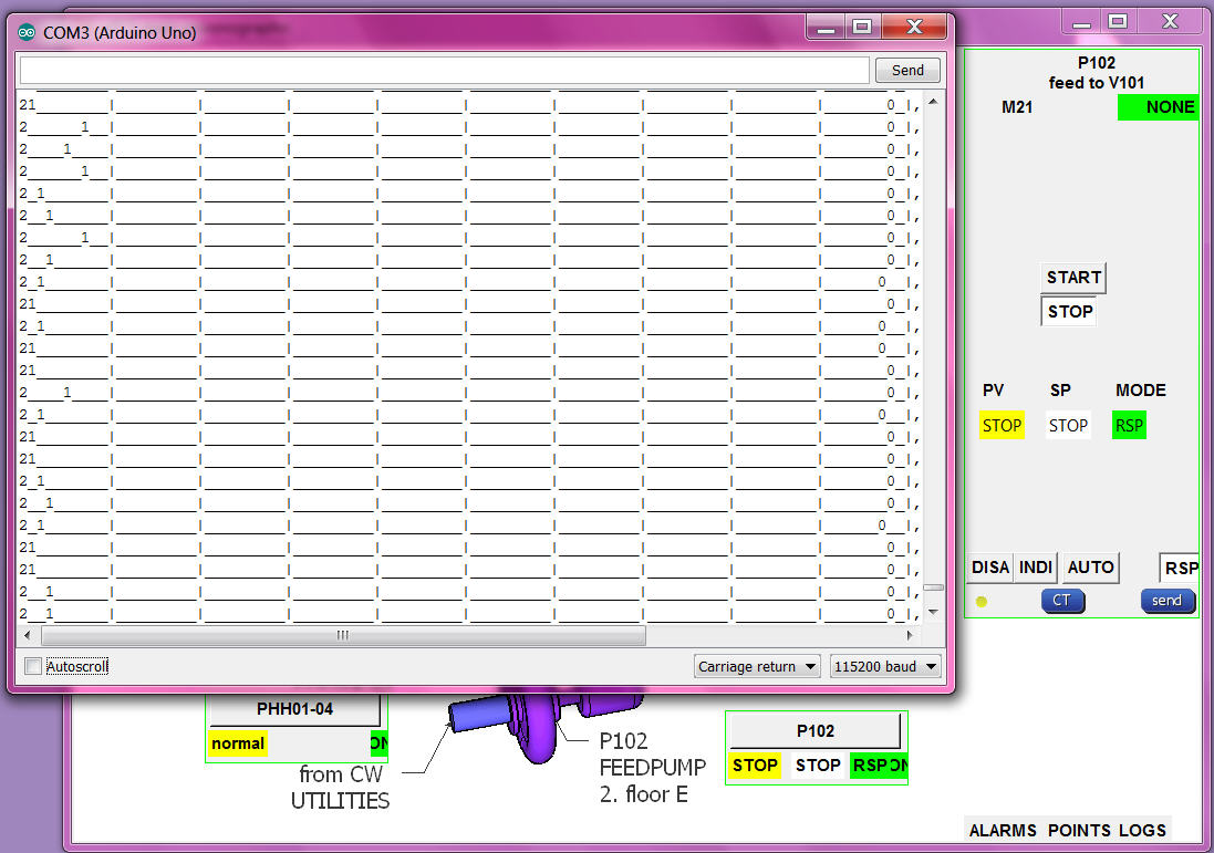
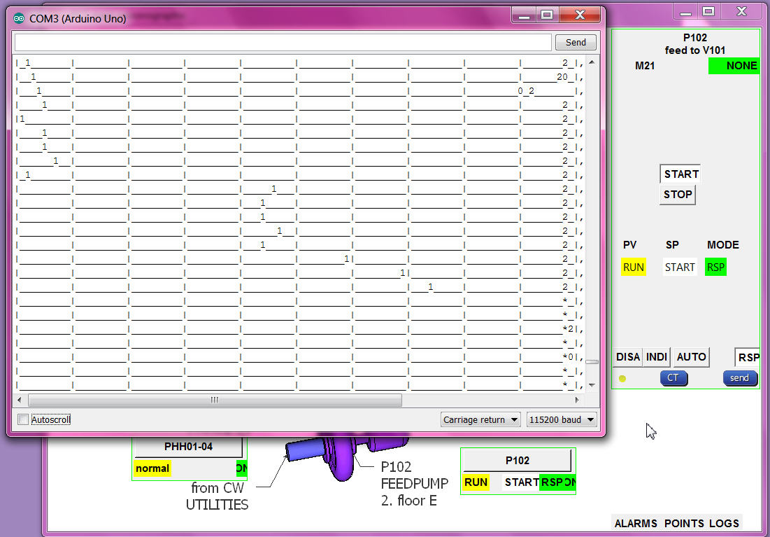
from the input pins ( their levels ) to the input combination, to the PV enumeration, transport to operation, translated to words (OK)
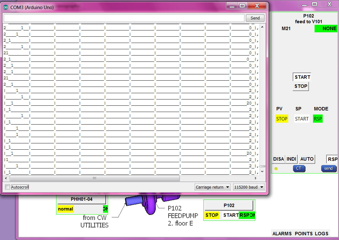
RSP setpoint button/word to RSP number send to arduino and drive output (OK)
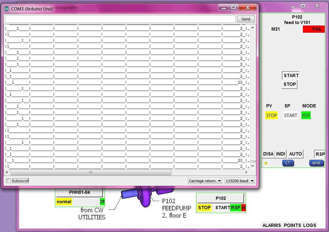
but the alarming needs a more detailed check:
RSP:
if PV RUN and SETPOINT START alarm "NONE" and then the PV goes to STOP alarm go "FAIL" (OK)
if PV RUN and SETPOINT START alarm "NONE" and then motor fault goes OFF and run still ON, the PV goes to UNDEF alarm go "ALARM" (OK)
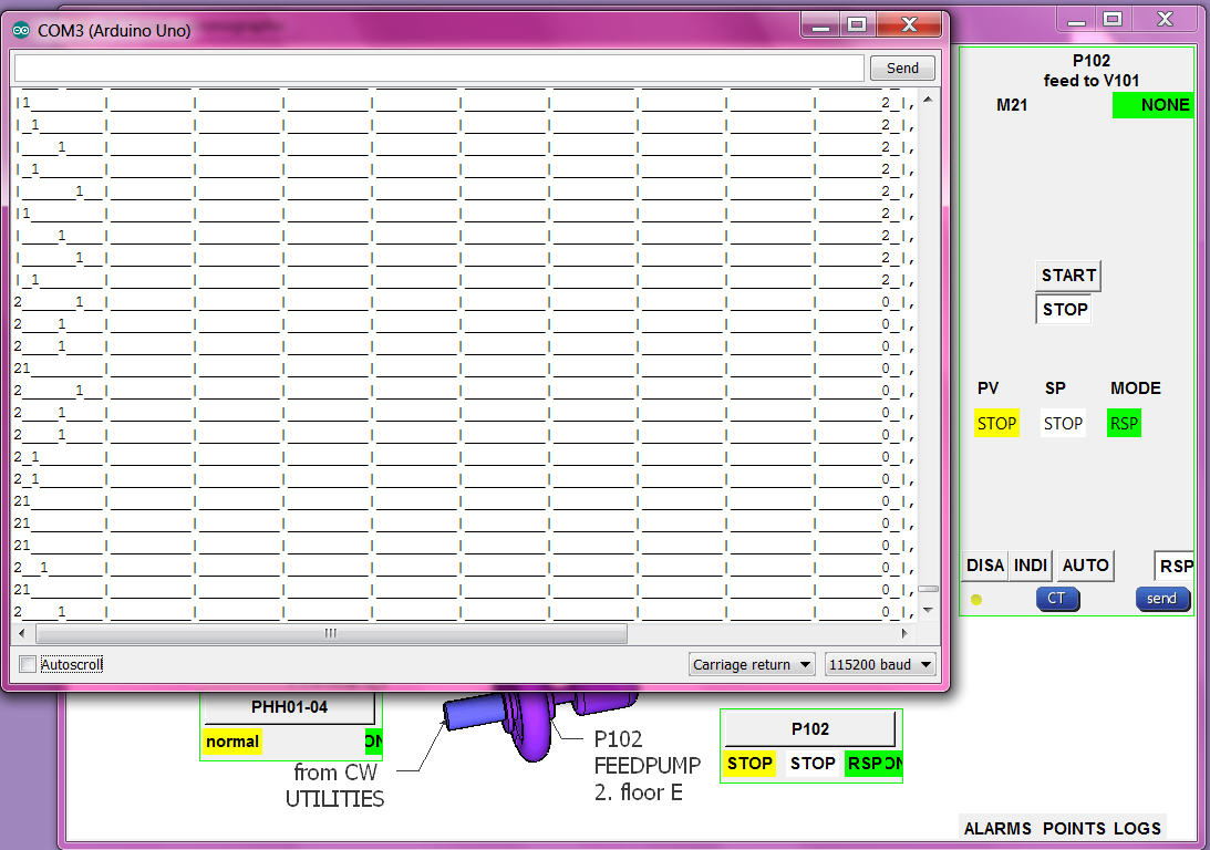
if PV STOP and SETPOINT change to START alarm "NONE" .. after delaytime "FAIL" (OK)
AUTO:
if MODE AUTO and SETPOINT STOP and then local setpoint input goes HIGH, SETPOINT goes START, OUTPUT HIGH, if PV not follow ALARM FAIL. (OK)
if MODE AUTO and SETPOINT START and then local setpoint input goes LOW, SETPOINT goes STOP, OUTPUT LOW, if PV not follow ALARM FAIL. (OK)
if MODE AUTO the RSP setpoint buttons in faceplate are confusing (NOT HAPPY)
but if i hide them with what setpoint go back RSP mode??
INTERLOCK:
if PV RUN and SETPOINT START alarm "NONE" and then the PHH goes to alarm, MODE go to INTerlock, OUTPUT goes OFF, (OK)
_ _ also can not change mode (OK)
_ _ but SP show UNDEF and no alarm (NOT OK) ! now show SP STOP, MODE INT, alarm ALAR, (OK)
_ _ when PHH ok can send RSP and SETPOINT again. (OK)
DISABLE:
SETPOINT START and change MODE to DISable (0) output still HIGH (NOT OK) ! now same as MODE INT, OUTPUT goes OFF, (OK)
- control hardware uPCS should run on chipKIT MAX32 also (OPEN)
partslist
arduino DUE
arduino MEGA
arduino Leonardo
raspberry PI B
RPI camera
RPI WIFI
BELKIN 4 USB 2.0 HUB + 2A poweradapter!?
DS18B20
SERVO SG91R
as this uPCS is just a template it is not very useful to make a circuit drawing, and its also difficult regarding using DUE or MEGA,
The PID on UNO with google historic trend is a real project from a friend / i still wait for the pictures /
this uPCS is more a study about the capabilities of arduino DUE and RPI.
but i think about how to do a good I/O ( input/output ) list for that project, or better how to make a back documentation from the arduino as easy TAG / I/O address list.
menu "P" is the point documentation
menu "I" is the I/O documentation ( to use from arduino terminal only)
i copy it to online google spreadsheet here