ARDUINO a new hobby
Posted by kll on February 21 2013 22:45:49
You heard of it?
ARDUINO
a easy and cheap playground with microcontroller
from ATMEL, AVR ATmega.
0. new computer
for play with microcontroller i wanted to have an extra computer,
i had a case from an old burned out desktop, cleaned it
and put it on the desk of the bananaIT shop nearby. with
-- CPU AMD Athlon II X2 250
-- 2GB/1333 DDR3 Ram
-- AsRock N68C-S UCC Motherboard
( has still a RS232 port, good for play with experiment boards )
-- PS 500W
i had a new one, for exact 5000 THB, about 120€ (service free!)
lucky, an old harddisc still worked, a external DVD from the netbook
helped for startup. installed:
++ win 7 ( update manually )
++ AVG FREE
++ SKYPE
++ OPEN OFFICE
+++ and TOTAL COMMANDER
( i grew up with NORTON Commander under DOS and never use windows explorer )
++ made FULL BACKUP
ready for rumble
1. order hardware
for beginning i ordered a
- arduino uno (older version: arduino duemilanove )
- proto shield kit ( to build own add on board )
here in thailand i contacted:
Electronic Source
they sell a ARDUINO duemilanove copy named FINO328 ( MLT-14103 )
(delivered with CD ) for 1100THB
board and info PDF does not contain any company information or
arduino info, it comes from MLT
and the official arduino distributor for thailand:
THAIDUINO
sell ( since this week) a ARDUINO UNO original, no CD,
( but with free USB cable and breadboard ) for 1130THB
online / email order , communication, bank transfer, EMS delivery with trackingcode,
all very good and fast (max one week)!
2. download software
download newest version from arduino
(ver 0021 as 85MB ZIP )
and copy/unzip to any workpath.
3. first tests
plug in usb cable
one green LED "ON" on, one yellow LED "L" blinking
looks like some blink software installed already ( factorytest)?
windows: device driver software was not successfully installed / no driver found
according manual go SYSTEM DEVICE MANAGER but my computer did not open that???
and did not even shut down... RESET!
restart and open device manager
plug in usb cable
under Other devices find Arduino Uno ( not like manual under PORTS)
do UPDATE DRIVER SOFTWARE and
use the arduinoarduino-0021drivers dir
there the inf file is in ( what is not visible in that window)
( no subdir , thats for other serial chip FTDI)
and make windows to accept that.
only then u see ( after "successfully updated your driver software Arduino UNO")
under PORTS (COM & LPT) .. ARDUINO UNO (COM3)
well good, ahm, how to check that connection???
i start ARDUINO software
-tools -serial port : change to COM3
-tools -serial monitor
adjust 57600 baud ( after many tests) and
start -serial monitor again, wait 4 sec and
i see between some funny characters following text
"StandardFirmata_forUNO"
on typing no reaction on terminal screen,
( expected some answer or echo )
but on board yellow blinking stops until shutdown terminal software ?
whatever was already loaded, its gone
i loaded my own blinking example successfully,
and initialized serial port in setup like code:
Serial.begin(57600);
Serial.println("HI KLL");
4. training
with a small command menu
(input numbers from 1 .. 9 )
i have now a test operation from PC
to select different test codes.
1. ramp up PWM output pin 9 ( to LED1 )
2. ramp up PWM output pin 10 ( to LED2 )
3. reset PWM outputs
the digital outputs PWM give 0. to 4.6 VDC for analog.write(0 .. 255)
possible PWM pins are 3,5,6,9,10,11
and should drive max 40mA ( or pin / micro dies )
an orange LED with 220ohm shows 2 VDC at 11.3mA
an blue LED with 100 ohm shows 3.4 VDC at 11.5mA and very bright
5. read analog poti A0
6. read analog poti A1 PWM output pin 10
because analog read range 0 ..1023, PWM output range 0 .. 255, devide by 4 !
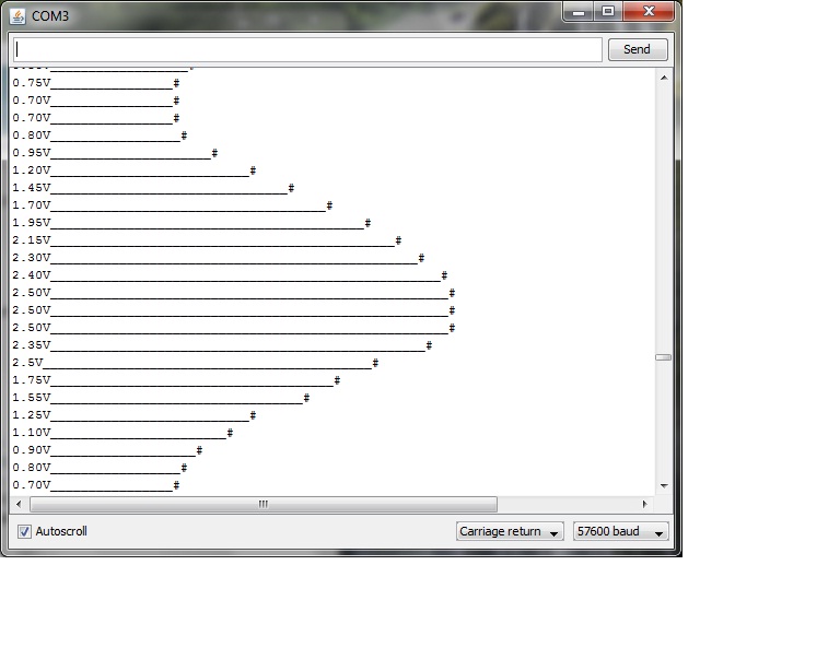
the indication on terminal is in 0 .. 5.0V (Volt)
and a long line of characters kind of bargraph, length depending on reading
like an old signal recorder.
9. time
the arduino uno has no real time clock (RTC) but a tick clock
and the "millis()" function
for test i build my own print_time function
( day, hour, min, sec since start board / reset to terminal /start terminal software)
There is an issue about the build in terminal function, read more about it at forum...
-- start of terminal software reset arduino board ( why is then no reset button in the
operating software from arduino, if it is obviously possible to do a reset via USB.
( i found it by using my time function )
-- each time i load code to the board the terminal closes automatically.
-- after i get a good external terminal software "hterm"
i see there is no reset on the board if i start that software hterm,
but if i want to load code i have to close hterm first!
from that status here
foto wiring
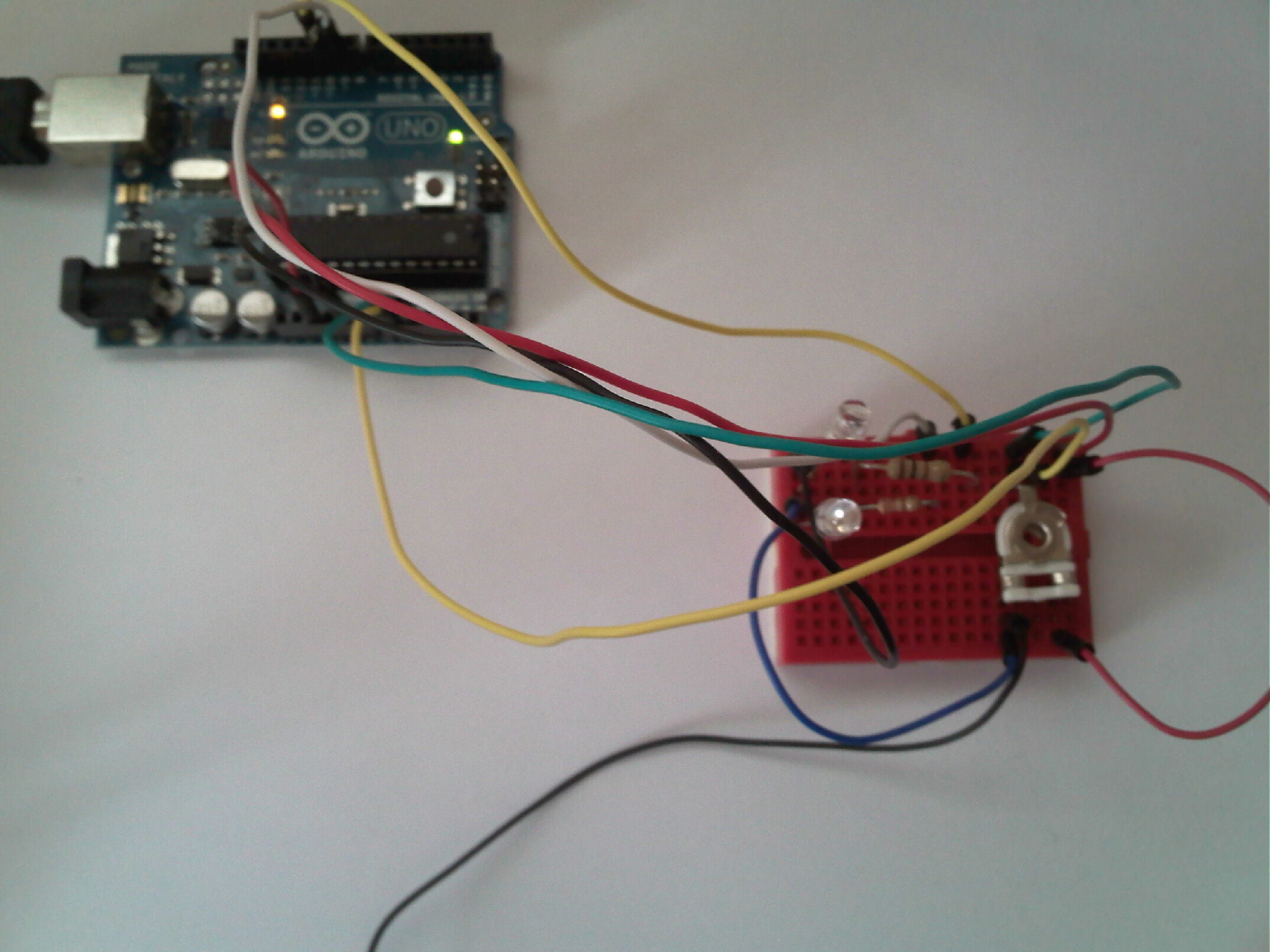
foto recorder function screenshot
Working on the menuprogram i tested about the timing, using the time function ( from millis)
and a new loopcounter.
the structure with checking interrupt from USB and a menu / switch case / structure
without doing any job ( where then delay timer are used... ), only the counting,
shows a speed of 1 000 000 loops in 23 sec.
In a copy of the program i deleted all functionality, just keep loopcounter and show time after
1 000 000 loops, i found 2 seconds.
here the list of some instructions and the time (sec) needed to do them 1 000 000 times
basis counter 2
add if question 2.5
analog in 112
serial.available() 19
i dont know if it is about the 2 chip coupling ATMEGA8U2-MU to ATMEGA328P,
or arduino (core) specific, even if i find the code behind that function
i would not understand it.
yes, its good to search the ARDUINO Forum
now ( in v0.3 ) there is
-- no delay function used in the main loop.
-- the usb is only checked every 1000 loop cycles
-- each conti main function has a loop counter and its excecution is adjustable every n cycles
-- usb speed is 19200, other speed have to check again,
-- a setpoint input via usb ( as integer number ) manually coded
( i am still not on the level to use interrupts, processes and firmata... )
so, unless it runs in the menu operation,
-- the mainprocesses need now about 10sec per 1 000 000 loops.
-- structure now able to do parallel jobs,
where each job is time-sliced by its counter.
-- more utility entries in menu: time, dignostic print, show variables, ASCII table.
A cleaned up version of the menu here
5. Analog out
ok, this processor not has a analog output DAC, so many ARDUINOS
( is that how to call ARDUINO developers? )
tried to use digital outputs for this.
above i already used the PWMs for LEDs,
but i found in the ARDUINO forum / playground ... very interesting stuff,
mainly using 2 Douts ( not PWM ) to different resistors
to generate a composite videosignal ( 1k, 470R assuming a 75R in a videoinput like TV ).
add audio from a digital output is also possible. pls see VIDEO GAME and
on ARDUINO
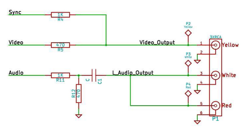
i test:
pin 9 SYNC PWM, 1kohm
pin 8 VIDEO HIGH LOW pulsing by code, 330ohm ( about 10mA )
over 100ohm to GND.
sync PWM 50% (125) gives 0.17V
video HIGH 1.05V, puls by delay ( 10 / 10 ) 0.5 V
i read that the PWM is adjusted to 490Hz basefreq.
some patches to change that i still have to test, but without a good oszi how to check?
please read next about project DMX