ARM7 WHAT IS THE SOFTWARE WITHOUT THE HARDWARE
Posted by kll on February 21 2013 22:42:08
here u see info and log about my work with ARM 7,
my first project using micro controller hard and software
0.0: from my last job i am used to buy big computer networks for data collection / industrial control so called
Distributed Control Systems (DCS)
but even that there was a programming level called HIGH ASSEMBLER
( or function sequence tables ) on the low end, it was never real programming,
the correct word would be CONFIGURATION.
And i not even know what processors are used in that hardware controllers and
I/O cards.
0.1 Now as i am retired and i think about that last 20 years engineering
i feel like i used a washing machine without ever thinking what makes it TICK.
well yes, yesterday i opened a washing machine, i throw some cloth in and pressed the start button.
I like the program setting FUZZY! what ever THAT means.
There is a strong interest in "micro controllers" for years already,
but when there was a requirement for a small 1 channel data collection
( a DC current over some days / weeks , may be sample time 10 min.. )
i had a reason to dig into it again.
If i can not build something like that myself, i am in good company,
but anyhow its a good way to start a new hobby ( for learning ).
1.0 SHOPPING:
not understanding what i do i selected the ARM 7 controller family
( thinking it might give me most options for future, but still affordable )
When you start with a trainings board you pay for it.
But when i see that there is already a SD memory card slot build in,
i decided its worth it.
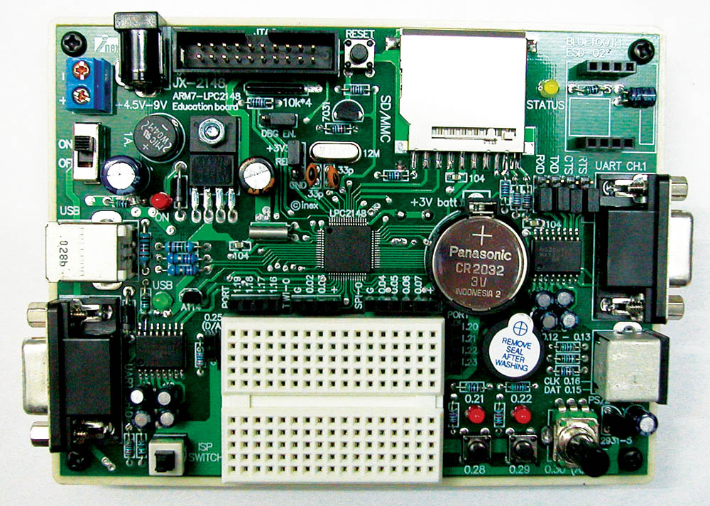
1.1 the JX-2148 LPC2148 Education board from
I nex for 2124 Baht, about 45 Euro.
s*t, forget the powersupply and the documentation about (+) (-) is confusing.
1.2 But for deep program check need some more toys,
a JTAG , there is a affordable copy product from micro4you
i got it from ThaiEasyElec for 1659 Baht incl delivery in Thailand, about 35 Euro
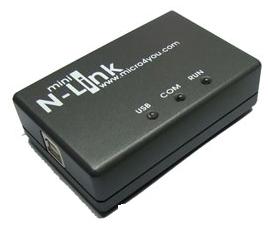
( if you check the vendors you will find prices like
JX2148=121 US$ and N-link=49 US$ )
2.0 SOFTWARE
2.1 SUN JAVA
HEY GUYS, PLS MAKE A WEBPAGE FOR DUMMIES LIKE ME
download jdk-6u3-windows-i586-p.exe 69 MB not used
well that is for what? i dont know, but its not what i wanted,
i just needed a JAVA RUNTIME ENVIRONMENT UPDATE.
download jre-6u3-windows-i586-p.exe 14MB
and installed.
2.2 ECLIPSE
eclipse download
eclipse-SDK-3.3.1.1-win32.zip 148 MB download but not used
and GnuArm Tool Chain
YAGARTO
openocd-2007re231-setup-rc01.exe 2.6 MB
yagarto-bu-2.17_gcc-4.2.1-c-c++_nl-1.15.0_gi-6.5.5_20071117.exe 30 MB
yagarto-ide-20070909-setup.exe 62 MB ( this already contains a older rev of eclipse )
all installed and tested ( pls see HOW TO pls check all 3 pages).
so i did my first compilation.
but debug ... not tested, because the N-LINK USB JTAG i have,
is not in the list of devices.
Now i check the CDs from MICRO4YOU and I-NEX again
and in forum i see: mini N-Link used with Keil Realview IDE.
and also the board info talks only about Keil software.
was all this downloading a waste of time? ( dont say, if i am retired i should have time,
thats wrong, actually then you are running out of time )
2.3 there is serial cable from PC to UART0 of the board
and with the LCP2000 PHILIPS FLASH UTIL you can download the compiled program
XXX.HEX ( made by 2.2 gnu, eclipse .. or 2.3 KEIL ) to the board.
Philips Flash Utility Installation.exe 2.94 MB install
RS232 cable from PC to UART0, power up, press reset, test all
--- can not communicate with board,
--- device (say LCP2106) can not be changed / selected
( i think its wrong software / cable bad / my PC COM PORT
(not port 1 ) or damaged / already want buy a new computer )
again (after study circuit drawing ):
connect cable, PRESS ISP SWITCH (shaft down ), power up ( red LED on )
start philips flash util program
COM 1, 9600 Bd , timeout 5 sec, select USE DTR/RTS
PRESS BUTTON READ DEVICE ID
and get back DEVICE, PART , BOOT LOADER info
WOW, THATS THE WAY I LIKE IT
There is the MENU
BUFFER / FLASH BUFFER OPERATIONS / button DOWNLOAD FLASH
! this means download from flash to PC !
means i want to read out the original program
( and UPLOAD to FLASH means programming )
and SAVE TO FILE.
means, before i overwrite the flash with my OWN program, i want to save the existing version. ( as HEX file)
What i noticed,
with ISP not down! power up
when i press the play push buttons at the board the LED goes ON ,
press again, LED OFF.
means there is already a application program ( what can do more???)
but that functionality is not in the LAB examples. ( may be in the thai manual
what is difficult to read for me )
a test with HYPERTERM COM1 9600 8 N 1 ANSI
show that on connection with
UART1 some text regarding A/D from poti is running.
UART0 might be for the terminal function with PS keyboard
( i can not test now ).
2.4 KEIL software
This is a development tool inclusive compiler and
with a JTAG from KEIL also a debugger.
from micro4you CD run
mdk305a.exe
( see Howto.pdf for more installation info )
USBDrivers.EXE
( see manual.pdf for more installation info )
now plug in the N-LINK USB cable to PC
and the usb JTAG will install.
Now adjust KEIL uVision 3 to work with "U-LINK JTAG"
so now i need a break,
i dont have a project and so can not test the connection and download
what according some forum info anyway will not work.
While i copy projects from examples from CD, internet...
run into the problem that KEIL use a different type of STARTUP.S
mainly all comments "/" are again UNCOMMENTED by ";/"
if not get lots of compiler errors.
after compile a KEIL EXAMPLE
-- MEASUREMENT
i test the upload , in KEIL called "LOAD" "download to FLASH"
and got communication error
so i was already thinking i run into the board problem as described in forums;
but i dont give up so easy
again poor circuit drawing by I-NEX
but i changed DBG EN jumper from ii_i to i_ii, press ISP (shaft down), power on
and the flash programming via N-LINK JTAG worked.
( and very fast ).
( this application has a nice measuring operating menu on UART1 )
Because that is mainly what i want to play about, that example will be my further basis.
Also the DEBUG works, but i dont thinks its something for beginner like me.
BUT NOW I CAN START THE REAL PROGRAMMING WORK.
3.0 work
3.1 project: data recorder with JX-2148
--workspace "JX-2148"
--project "measure"
i want adapt the keil program example * measure *
to the I-NEX board.
3.1.a level 1: use the existing hardware
UART1 for HMI ( optional operation menu )
--LED1 0.21
--LED2 0.22
--PB1 0.28
--PB2 0.29
--poti 0.30
--piezo 0.12 0.13
prepared connections:
--DA 0.25
--P0.02 .. P0.07
--P1.16 .. P1.23
first there is the problem that the KEIL program use
0.25, 0.28, 0.29, 0.30 as 4 analog inputs
in level 1 i want use the existing hardware ( trainings board )
as it is, so reduce the program to
** sample only 0.30 POTI ( makes it faster )
** buffer length 512 ( for osci screen or excel courve )
** R readout to UART1 that with TEXT CAPTURE get CSV file for EXCEL
** use LED (and PB for operation),
LED 0.21 ON indicates recording (S) is running ( (Q) OFF )
LED 0.22 indicates the sample time ( if sampled every second,
led is 1 sec ON and 1 sec OFF )
** change UART1 speed to 19200.
** SD CARD test
ok, detect card and read header data ( and calculate size of card )
but read / write of BLOCK seems not to work.
NEED A FILE SYSTEM??
i will look into EFSL
the filesystem is a separate project, i try some time to get it compiled
and now i have a problem to get it running, ( the download is ok,
but still the old program is running, and not the new with the EFSL ??? )
RAM/ROM....memory config.
but good news, the REAL TIME CLOCK RTC works,
after connect to external crystal and start its very helpful,
( JX-2148 has crystal and battery ON BOARD )
so the old SET TIME function ( on TIMER0 )
is now replaced by SET RTC TIME ( if needed )
and at systemstart / reset the TIMER time is set by RTC time.
now to get closer to easy operation for a FIELD DATALOGGER
( when no computer available )
-- the 2 push buttons on interrupt
* PB1: start datacollection
* PB2: stop
later there must be save all data to SD card.
-- the sample rate ( now max 1 kHz )
* try to get it faster ( only for osci function )
After change of datastructure to:
TIME hh:mm:ss.mmm.uuu now show mircoseconds
A00 / A03 only 2 analog channel log
and change of timer / interrupt, now tunable in microseconds
the limit seems to be at
10 micro seconds / 100 kHz
then the timer in TC0 and even the RTC start to go wrong ???
with only the timer job, even with one ADC, it still work, but with storing the data
to the array the time between 2 interrupts seems not to be enough.
also some occurrences while "measuring display" incl. program hangup was noticed.
-- measuring hardware
* start building a OPamp circuit for amplification of the
SHUNT 50mV at 50A DC current measurement.